
Crane Rail Fastening System Selection Guide
Complete reference for choosing rail clips, rubber pads, bolts, and steel soleplates, tailored to overhead, gantry, and port cranes.
Why Rail Fastening Matters
The crane rail fastening system is the load‑transfer hub connecting wheel loads, the rail, and the supporting structure. A poorly configured rail clip or an incorrect rubber pad can lead to lateral displacement, abnormal wheel flange wear, and even safety incidents. In one heavy‑duty workshop, a QU80 rail fixed with ordinary bolts shifted 15 mm laterally within six months, causing severe flange wear and an emergency shutdown.
A complete system consists of four core components: Rail Clip, Rubber Pad, Bolt, and Steel Soleplate — supported by grout and rail welding.
Rail Selection
The rail profile and material dictate all downstream fastening choices. Key standards include QU series (China), DIN 536 (Europe), and railway P‑type rails.
QU Crane Rails
The QU series crane rails are manufactured according to the YB/T 5055-2014 standard, primarily in U71Mn steel with a tensile strength of up to 880 MPa, designed specifically for heavy lifting equipment. The four main specifications are:
| Type | Height A (mm) | Foot Width F (mm) | Head Width C (mm) | Web Thickness t (mm) | Cross-Section (cm²) | Theoretical Weight (kg/m) |
|---|---|---|---|---|---|---|
| QU70 | 120 | 120 | 70 | 28 | 67.30 | 52.80 |
| QU80 | 130 | 130 | 80 | 32 | 81.13 | 63.69 |
| QU100 | 150 | 150 | 100 | 38 | 113.32 | 88.96 |
| QU120 | 170 | 170 | 120 | 44 | 150.44 | 118.10 |
The QU series features a square, high-profile design (foot width ≈ rail height) that provides a large contact area and strong bending resistance. It is widely used for overhead cranes, gantry cranes, and large port equipment.
DIN 536 Crane Rails
DIN 536 is the European standard for crane rails. Its profile characteristics are “narrow head, thick web, wide foot, and low height,” which fundamentally differ from the QU series. There are seven common models from A45 to A150; the model number indicates the head width in millimeters (e.g., an A120 rail has a head width of 120 mm and a foot width of 220 mm). DIN 536 rails are widely used at port terminals, shipyards, and industrial plants, typically connected by welding or special joints, and are often installed with welded-type or bolted-type rail clips.
| Type of Rail | Rail Height A (mm) | Bottom Width F (mm) | Head Width C (mm) | Web Thickness t (mm) | Steel Grade | Weight (kg/m) |
|---|---|---|---|---|---|---|
| A45 | 55 | 125 | 45 | 24 | 50Mn | 22.1 |
| A55 | 65 | 150 | 55 | 31 | 50Mn | 31.8 |
| A65 | 75 | 175 | 65 | 38 | U71Mn | 43.1 |
| A75 | 85 | 200 | 75 | 45 | U71Mn | 56.2 |
| A100 | 95 | 200 | 100 | 60 | U71Mn | 74.3 |
| A120 | 105 | 220 | 120 | 72 | U71Mn | 100 |
| A150 | 150 | 220 | 150 | 80 | U71Mn | 150.3 |
Other Common Rails
P-Type Rails (P38, P43, P50, P60): Standard railway rails, suitable for small to medium-sized cranes.
CR Series Rails (JIS E 1103 standard): Japanese standard crane rails, with a profile similar to the QU series.
Square Steel Bars: Used for light-duty cranes, placed directly onto the support beam.
Core Basis for Rail Selection: Crane wheel load, travel speed, and duty classification. The greater the wheel load and the more frequent the operation, the larger the required rail cross-section.
Rail Clip Types & Selection
The rail clip laterally fixes the rail while allowing longitudinal thermal movement. Two main families exist: welded and bolted.
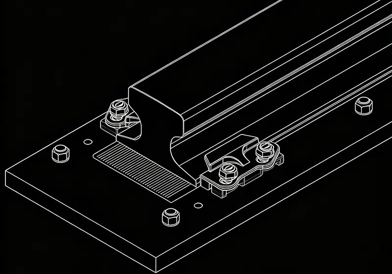
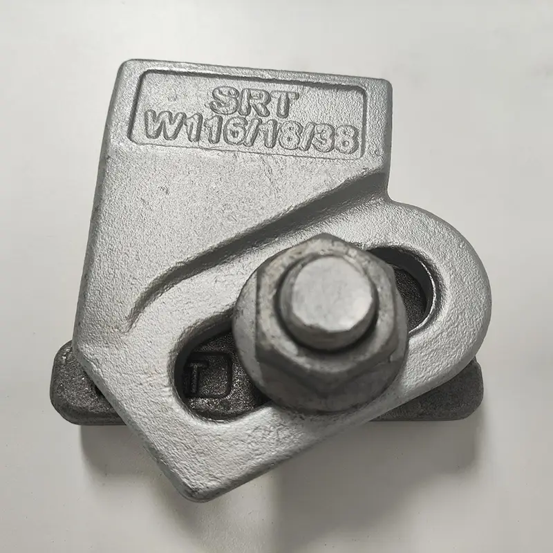
Welded Rail Clip
Base welded to the girder/soleplate. Ideal for heavy loads, high lateral forces, and dynamic conditions (metallurgical cranes, port cranes). Example: W120 clip resists up to 185 kN lateral force.
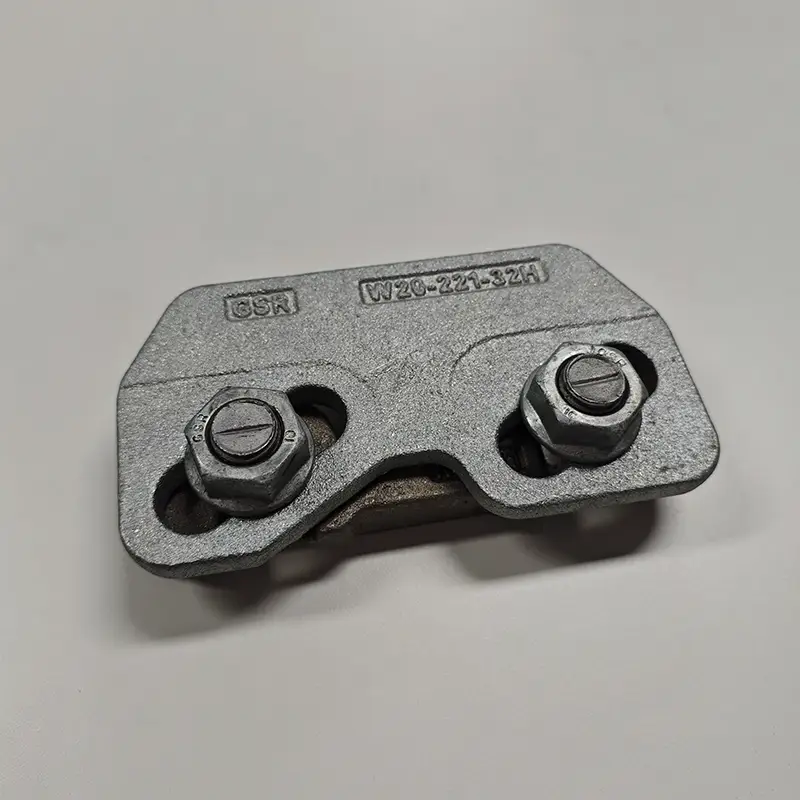
Bolted Rail Clip
Through‑bolted into pre‑drilled beam holes. Removable, adjustable, easier to maintain. Suitable for small to medium cranes and frequent maintenance scenarios.


Clip‑to‑Rail Matching
| Rail Type | Recommended Clip | Bolt Size | Notes |
|---|---|---|---|
| QU70, QU80 | Standard bolted / light welded | M20 | Small-medium profiles |
| QU100 | Heavy-duty cast (welded/bolted) | M20–M24 | Large profile, stronger lateral restraint |
| QU120 | Heavy-duty welded | M24 | Maximum tonnage, highest lateral forces |
| DIN 536 A45–A75 | Welded or bolted | M16–M20 | Light-medium duty |
| DIN 536 A100–A150 | Heavy-duty welded | M20–M24 | Heavy port applications |
Clip Spacing
Straight sections: 600–800 mm. Curves and rail joints: reduce to 400–500 mm. Spacing must be verified by lateral force calculation.
Materials & Finishes
Q235 forged, ZG35 cast steel, QT500-7 ductile iron, Q345 low‑alloy steel. Upper parts and bolts are hot‑dip galvanized; weldable bases can be bare (painted after welding) or pre‑galvanized.
Rail Rubber Pad
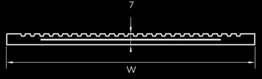
The rubber pad acts as a buffer: it compensates for unevenness, absorbs impact/vibration (up to 50% reduction), and evenly spreads wheel loads.
Steel‑Reinforced Continuous Pad
Embeds a 0.5–1 mm galvanized steel sheet to prevent rubber extrusion under high loads. Standard length 6–12 m rolls.
Standard Pad (No Steel)
For light to medium cranes, lower cost but less extrusion resistance.
Material Selection
| Material | Properties | Application |
|---|---|---|
| NBR (Nitrile) | Oil resistant, wear resistant | Indoor, oily environments |
| SBR (Styrene) | Good wear resistance, elastic recovery | General industrial applications |
| EPDM | UV, ozone, and weather resistant | Outdoor, port, high-temperature environments |
| EVA | High compressive strength, high damping | Heavy-duty, high-frequency operations |
Standard thickness: 7 mm (±0.5), temperature range –25°C to +100°C.
Bolt Selection & Torque
Bolts are the critical link between clip and structure. Glory Track bolted clips use Grade 8.8 or 10.9; welded clips have integral captive bolts.
Torque Specifications
| Clip Model | Bolt | Torque | Application |
|---|---|---|---|
| 3116 | M16 ×1 | 8.8: 200 Nm / 10.9: 300 Nm | Light crane runways |
| 3120 | M20 ×1 | 8.8: 390 Nm / 10.9: 600 Nm | Standard industrial |
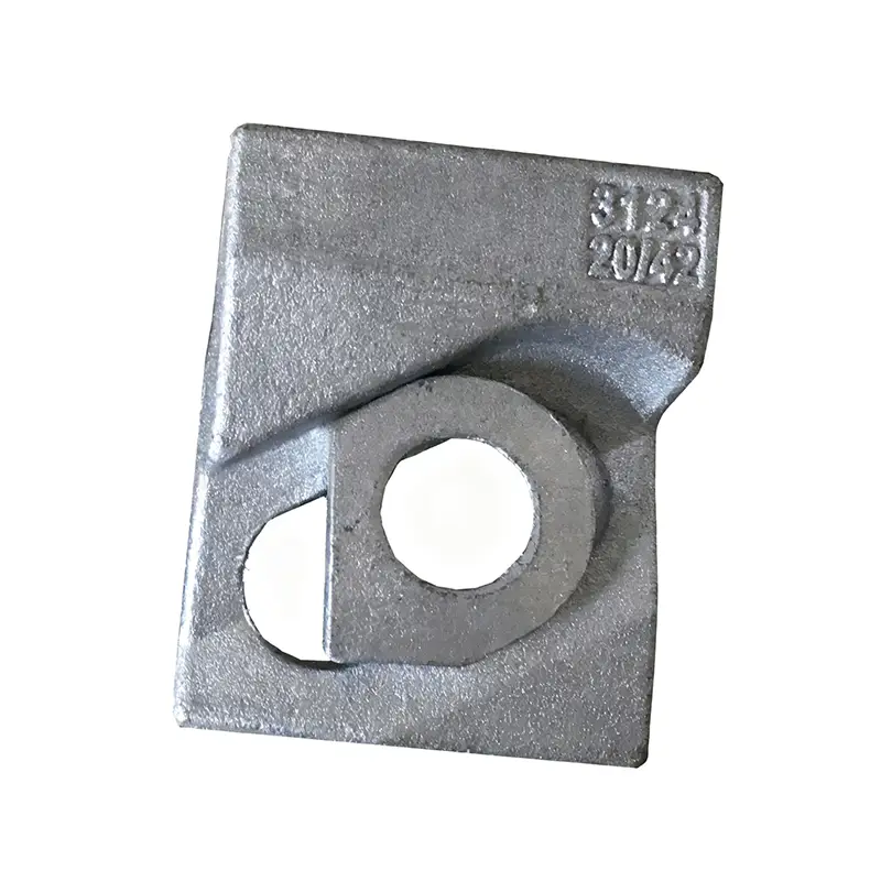
| 3124 | M24 ×1 | 8.8: 600 Nm / 10.9: 750 Nm | Heavy railway |
| 3220 | M20 ×2 | 8.8: 200 Nm / 10.9: 300 Nm | High-stress runways |
| 3224 | M24 ×2 | 8.8: 200 Nm / 10.9: 300 Nm | Heavy-load runways |
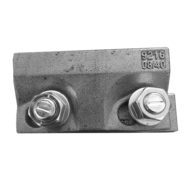
| 9116 | M16 captive ×1 | 125 Nm | Welded base, heavy |
| 9120 | M20 captive ×1 | 350 Nm | Welded base, heavy industrial |
| 9216 | M16 captive ×2 | 125 Nm | Double-bolt, extra heavy |
| 9220 | M20 captive ×2 | 350 Nm | Double-bolt, extreme heavy |
| TG50 | M24 T-head ×1 | 150–220 Nm | P50 rail, welded |
Corrosion & High‑Temp
Hot‑dip galvanizing (30–60 μm) for outdoor/port use. For metallurgical shops, grade 310S stainless bolts withstand 800°C. Re‑calculate torque considering thermal expansion.
Steel Soleplate
Provides a flat platform for clips and pads, transferring loads to the foundation. Two configurations:
Continuous Soleplate: full‑length plate (≥20 mm thick), best support and alignment. Used with welded clips.
Individual Soleplate: separate plates under each clip, economical on concrete, easy to replace.
Leveling shims: 6–10 mm Q235 steel, area ≥ 1.5× rail foot area, max. 3 shims per stack.

Common Mistakes & Maintenance
| Mistake | Correction |
|---|---|
| Ignoring lateral forces | Check horizontal guide roller forces; select clip rating accordingly. |
| Using same pad everywhere | Use EPDM outdoors, NBR for oil exposure, and EPDM for high-temperature environments. |
| Uniform 800 mm spacing | Reduce spacing to 400–500 mm at joints and curves. |
| Arbitrary bolt tightening | Use a torque wrench according to specification requirements (see torque table). |
| Shim plates without rules | Minimum shim area should be 1.5× rail foot width; maximum 3 shim plates allowed. |
Maintenance: Inspect clips for looseness, retighten bolts quarterly after commissioning, replace corroded/stripped bolts as a complete set, and keep pad area clean.