
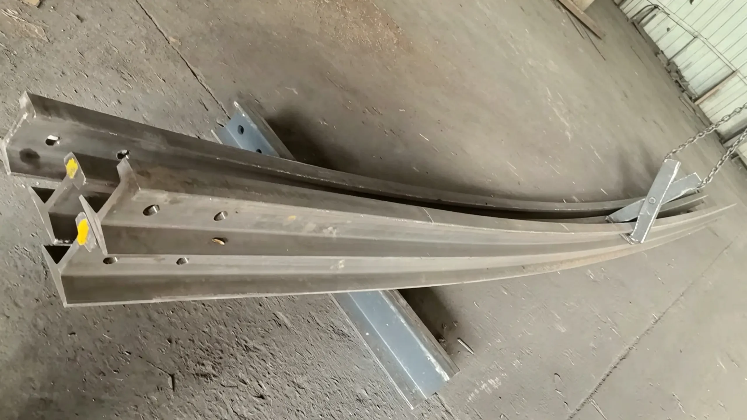
An Indonesian industrial components supplier required a vertically curved rail system for an apron conveyor tail section. The original design called for single-piece 12‑meter ASCE 60 rails. Because standard mill lengths come in 6, 8 and 10 meters, 12‑meter pieces would have generated cut‑off waste. Our team proposed a revised layout that split each 12‑meter rail into two 6‑meter segments bolted together. The client approved the new design, and the complete rail package—bent rails, W116 clamps and all documentation—was delivered with zero material scrap.
Client Background
The customer supplies industrial components to heavy‑duty material handling projects across Indonesia. This order was for the tail‑side rail segments of an apron conveyor, which transports dense, abrasive bulk material. The tail section requires a curved rail to turn the conveyor chain plates from the lower return run back onto the upper carry run. The rail profile is ASCE 60, specified in ASTM 900A/1100 grade for its wear resistance under continuous impact and heavy loading.
Project Requirements
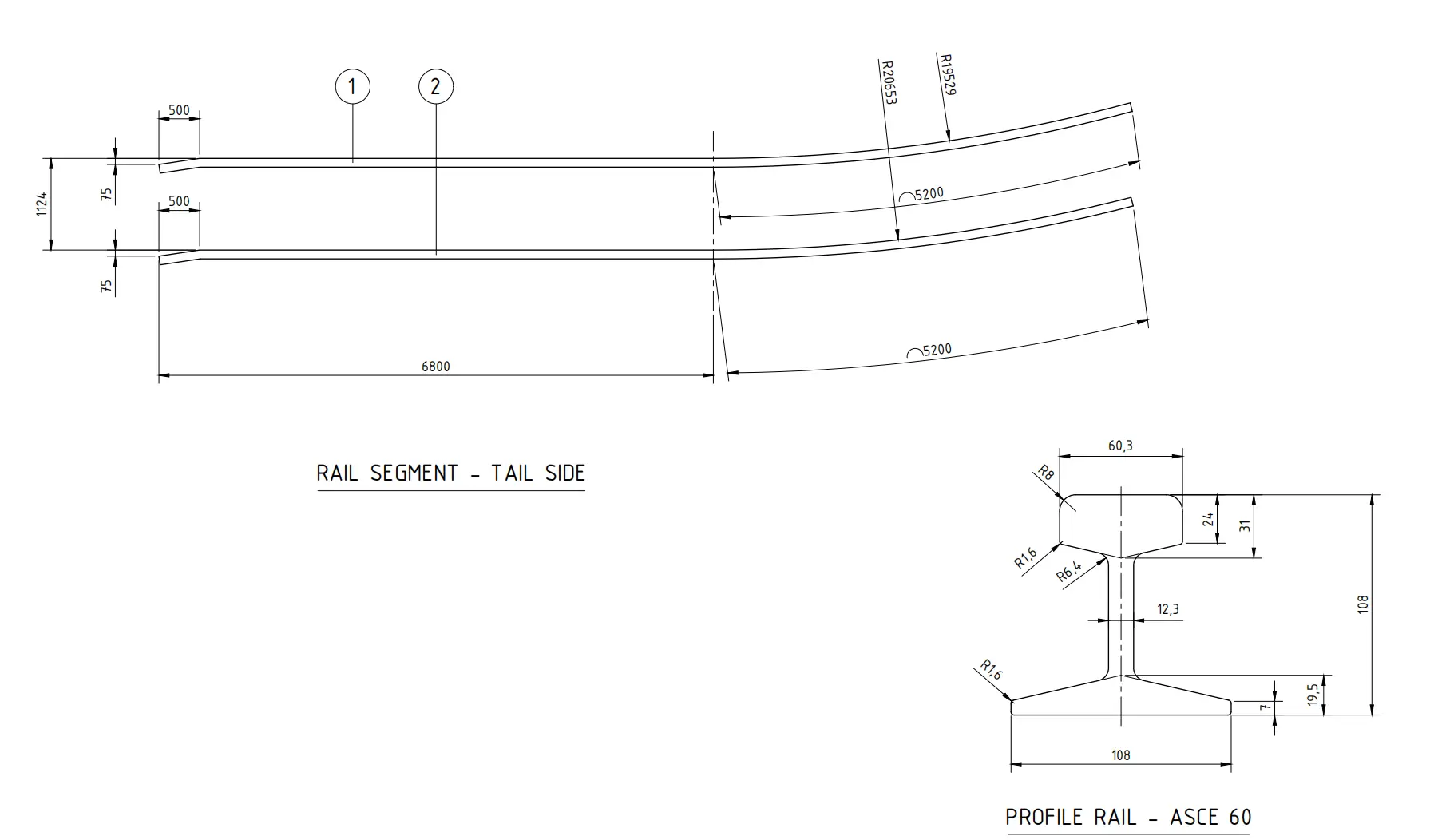
The client’s drawings defined two upper and two lower rails, each 12 meters long, formed from a single piece of ASCE 60. Every rail consisted of three integrated zones: a 500 mm straight end with a 75 mm chamfer for entry transition, a 6,300 mm straight guide section, and a 5,200 mm arc that performs the vertical turn. The upper rails required an inside bend radius of R19,529 mm; the lower rails an outside radius of R20,653 mm, giving a constant track gauge of 1,124 mm.
The 12‑meter one‑piece approach conflicted with standard stock availability and would inevitably leave offcuts. Cost control was important, so we looked for a way to meet the required total lengths without generating scrap. Beyond the geometry, the rails had to hold gauge precisely through the curve and withstand repeated impact loads at the transition. Fastening had to stay tight, and site assembly had to be straightforward—the installation crew expected components ready to place and fix.
Related Products & Services
Glory Track supplied the full package:
- ASCE 60 industrial rail – 30 kg/m, ASTM 900A/1100 grade for heavy‑duty wear conditions.
- W116 welded rail clamp – used to fix the rails to the steel support structure. Welded base with an elastic clamping element that absorbs vibration and prevents loosening.
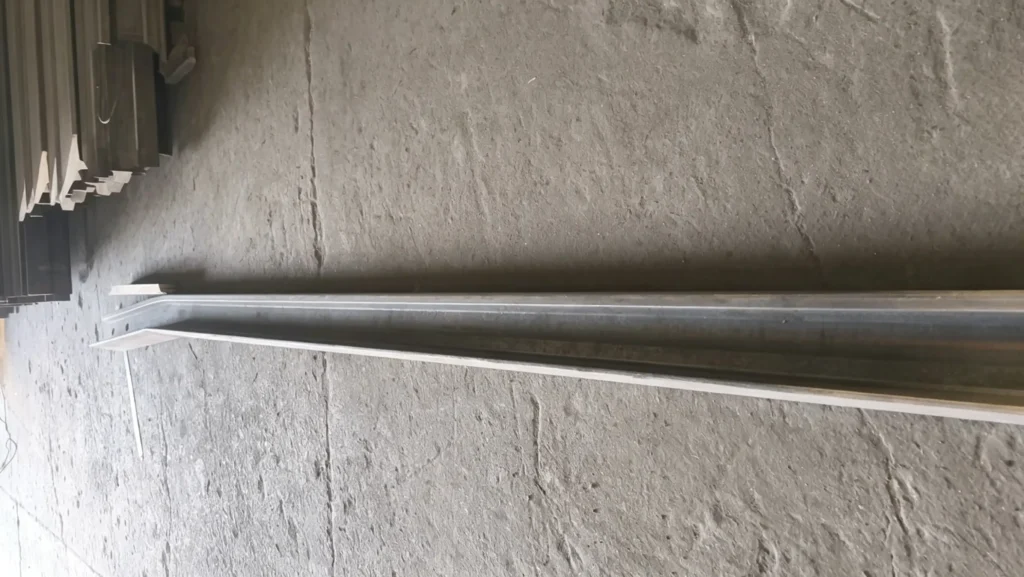
- CNC vertical rail bending – cold bending of each segment’s 5,200 mm arc to the specified radii (R19,529 mm upper / R20,653 mm lower).
- Re‑design and shop drawings – we converted the original 12‑meter one‑piece layout into a two‑piece 6‑meter bolted splice design, with fabrication drawings submitted for approval.
- Dimensional inspection – 3D measurement of every bent arc to verify radius, flatness and overall profile.
- End preparation – 75 mm chamfer machined on the lead‑in end of each front rail segment.
- Export packing – rails secured on purpose‑built steel frames to protect the curved geometry during ocean freight to Indonesia.
Project Challenges
Bending a 30 kg/m rail along its vertical plane requires careful process control. The profile is stiff in that direction, and any twist during bending would cause the chain plates to lean, accelerating wear on the rail top. The tight radius tolerance (±5 mm on R19,529 and R20,653) meant we had to verify the arc carefully after forming.
Because the tail section turns the conveyor chain under load, impact forces at the arc entry can be high. The rail fastening system had to hold the rail securely in place on the support steel and not work loose under repeated shock. At the same time, the on‑site crew needed rails that were pre‑bent, pre‑chamfered and clearly marked so they could be set in position and fixed without field modifications.
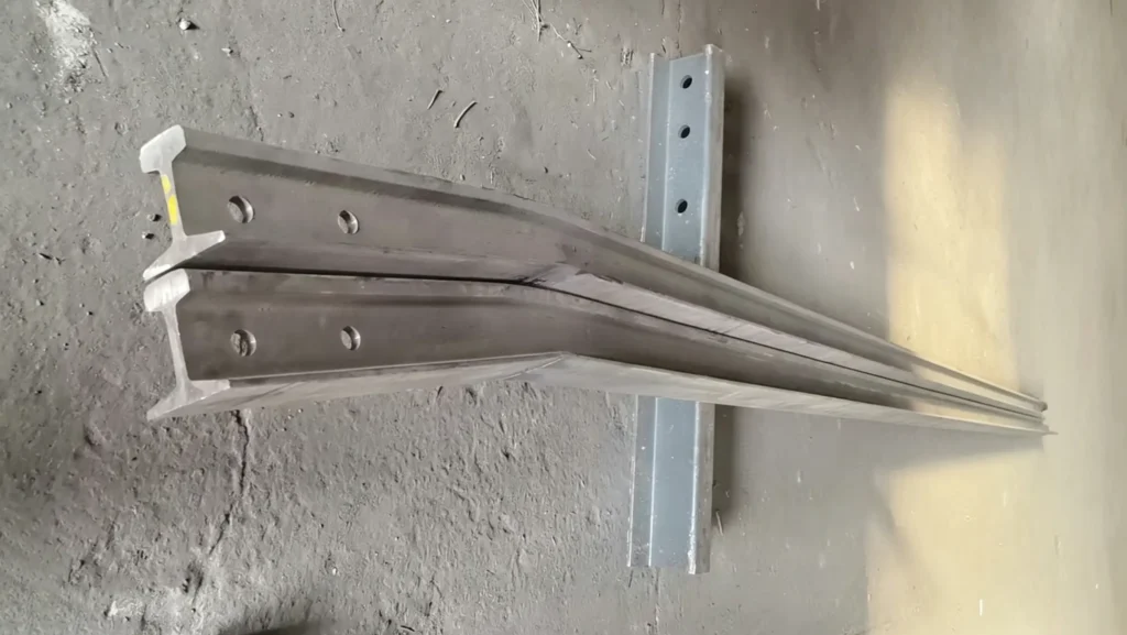
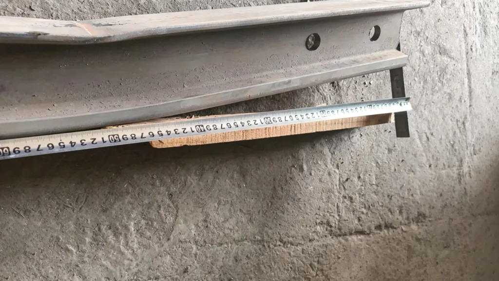
GLORY TRACK Solution
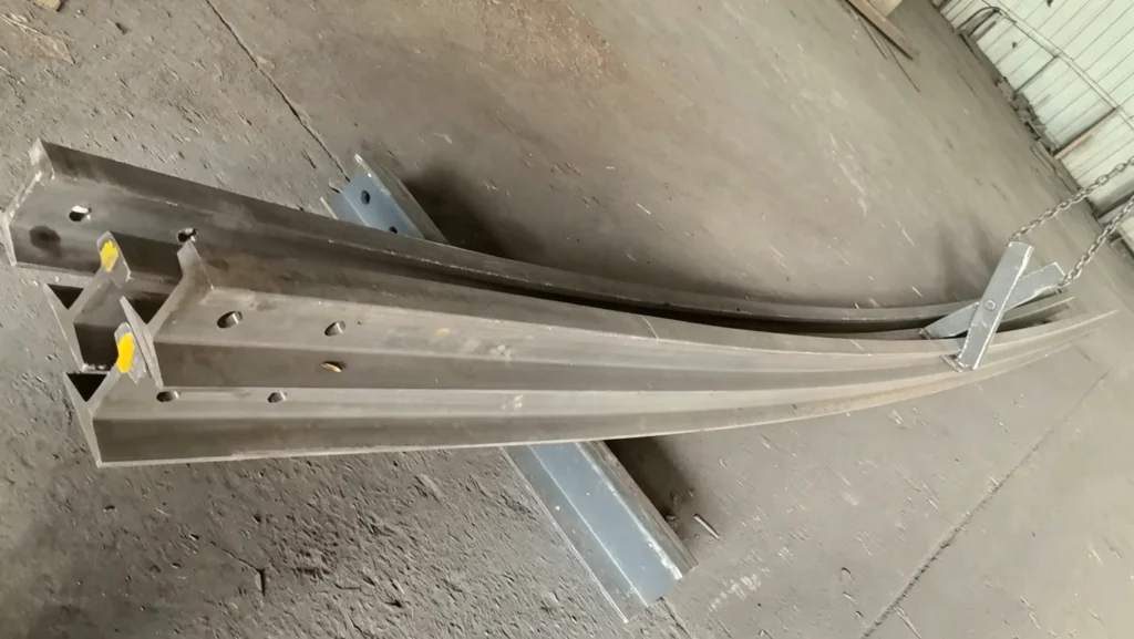
After reviewing the original drawings, we proposed a revised design: each 12‑meter rail would be made from two standard 6‑meter ASCE 60 rails, bolted together at a machined joint. This matched the available stock lengths and eliminated cut‑off waste entirely. The client’s main question was whether the splice would affect alignment or smooth running. We explained that the joint would be positioned in the straight portion before the arc, with machined connecting holes and bolt‑up plates keeping the rail faces flush. The W116 welded clamps would then lock both segments to the support structure, ensuring continuous alignment. Once the design logic was clear, the client approved the new drawings.
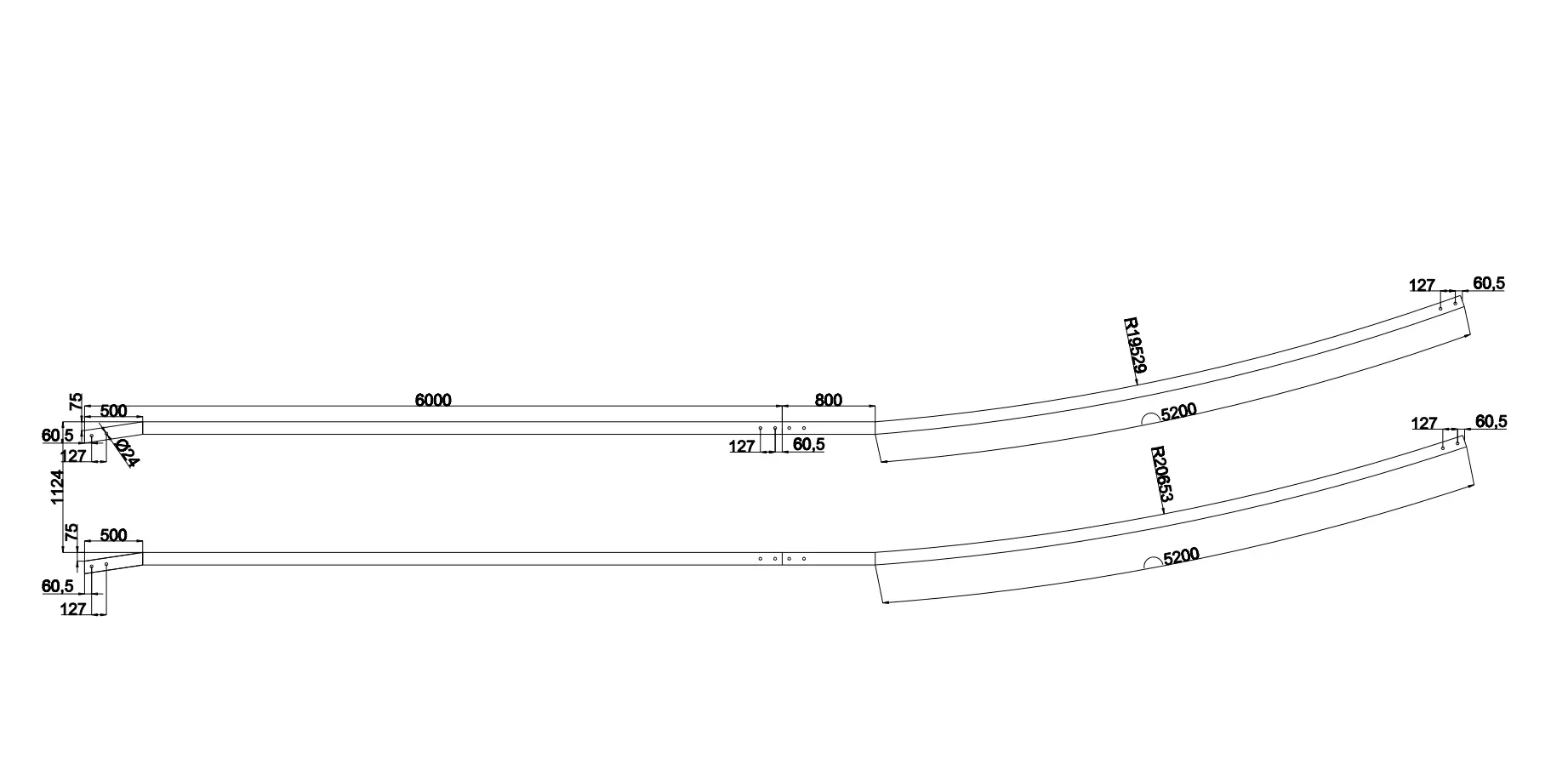
For the four finished rails (two upper, two lower), we used eight standard 6‑meter rail pieces. Each rail was built as follows:
- Front straight segment (6,000 mm, 1st rail): 500 mm chamfered lead‑in + 5,500 mm straight guide. Connection holes drilled at the rear end.
- Rear curved segment (6,000 mm, 2nd rail): 800 mm straight transition with matching connection holes, followed by the 5,200 mm arc bent to the specified radius.
Our workshop cold‑bent each rear segment on CNC equipment, then checked the arc geometry with a 3D measuring arm. Radii, flatness and gauge pairing were verified against the approved shop drawings. The front segments were kept absolutely straight, with the 75 mm chamfer machined as specified. All rails were marked with position and orientation to simplify site assembly.
The complete set—eight bent and straight rail segments, W116 clamps, connecting hardware, was packed on a steel frame that supported the curved profiles, and shipped to Surabaya.
Project Results
By switching to the 6‑meter splicing scheme, all rail material came from standard stock lengths with no cut‑off waste. The client avoided the cost of purchasing non‑standard 12‑meter pieces or paying for material that would end up as scrap.
All eight rail segments were used as finished product; nothing was discarded.
Dimensional inspection confirmed that radii, arc length, chamfer dimensions and track gauge all met the client’s original drawing specifications.
The order was completed and shipped on schedule. Using 6‑meter standard stock kept fabrication and packing straightforward.
On site, the pre‑bent and pre‑chamfered segments were easier to handle and position than full 12‑meter pieces. The bolted splice joints assembled without issues, and the rail alignment was correct once the clamps were tightened.
After installation, the client reported that the rail runs smoothly through the tail curve, with no shaking or misalignment. The W116 clamps have held firm without needing re‑tightening.
Why GLORY TRACK?
We treat every order as an engineering task, not just a supply transaction. On this project, that meant reviewing the original single‑piece design, drawing up a workable splice alternative that preserved every functional dimension, and supplying a complete package—bent rails, clamps, hardware, shop drawings and inspection data. Our in‑house CNC bending and 3D inspection give us direct quality control, and we manage export packing ourselves so the rail geometry remains protected during shipping. Clients deal with one team from drawing review to delivery.
Client Feedback
After the system was commissioned, the client sent a brief update:
“The rails fit well and the curve runs smoothly—no shaking or misalignment. The clamps are holding tight and we haven’t had to re‑tighten anything. The switch to 6‑meter splicing saved us material cost without affecting the installation. Everything arrived on time and the pre‑bent sections made setup much quicker than we expected. We’ll come back to you for future curved rail work.”
If your project involves vertically curved rails, non‑standard rail layouts, or heavy‑duty fastening systems, you are welcome to contact our team. We can review your drawings, suggest practical ways to reduce waste and cost, and deliver finished rails with clamps ready to install. Reach out to discuss your requirements.