
A crane rail expansion joint is designed to accommodate movement at a specified location in a crane runway. It is particularly relevant where the runway must account for movement in the supporting structure, such as at an expansion joint in a wharf or long runway beam.
Unlike a standard rail joint, an expansion joint does more than connect two rail sections. Its design must allow the movement required by the project while providing a suitable transition for crane wheels.
The rail profile alone does not determine the joint arrangement. The required movement, rail-end geometry, fastening system, and supporting structure all need to be considered.
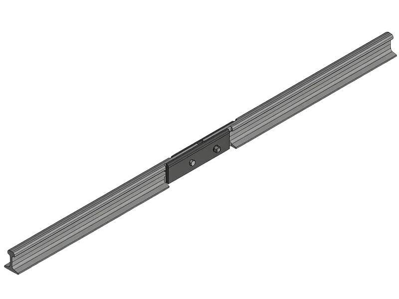
How Is an Expansion Joint Different from a Standard Rail Joint?
A standard rail joint connects adjacent rail sections and maintains alignment across the connection. Depending on the system, the rails may be joined using bolted joint bars or welding.
An expansion joint has an additional requirement: it must accommodate specified movement rather than simply form a continuous connection.
This distinction becomes important when the crane runway crosses a structural expansion joint. The rail arrangement needs to work with the expected movement of the supporting structure without compromising the rail transition or the crane’s passage over the joint.
Special designs may use tapered or angled rail ends, specially arranged base plates, and fastening components suited to the required movement. The exact configuration depends on the runway design; these features are not interchangeable across all applications.
A standard bolted splice or welded joint should not be treated as an expansion joint unless the approved design specifically permits it.
What Determines the Crane Rail Expansion Joint Gap?
The required gap cannot be determined from the rail profile alone. Temperature change, structural movement, installation conditions, and the rail fastening arrangement can all affect the joint design.
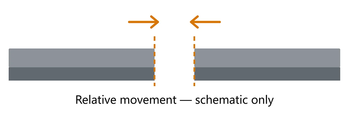
Rail thermal expansion
Steel expands when its temperature rises and contracts when it falls. The free change in rail length can be estimated using:
ΔL = α × L × ΔT
Where:
ΔL is the change in rail length.
α is the coefficient of thermal expansion.
L is the effective rail length.
ΔT is the temperature change.
This calculation estimates free thermal expansion. It does not, by itself, establish the required expansion-joint gap.
In an installed runway, the rail’s actual movement depends on how it is supported and restrained. Fixed points, rail clips, bearing pads, and other fastening details can affect whether and how the rail moves longitudinally. Movement of the supporting structure may also need to be accommodated.
The design therefore needs to establish the required movement allowance and the joint’s intended position within that movement range.
Installation temperature and joint setting
The temperature at installation can affect the joint setting. A gap suitable at one reference temperature may not provide the intended allowance at another.
For this reason, the project documents should identify the required installation setting or reference conditions where applicable. Installation teams should not have to infer the intended gap from a general arrangement drawing alone.
Slot length is not the same as available movement
Some expansion-joint assemblies use elongated slots to accommodate relative movement between connected parts. However, the slot’s overall length does not automatically equal the available travel.
Usable movement depends on the slot dimensions, bolt diameter and position, end clearances, restraint arrangement, and specified installation setting.
The same principle applies to the gap between rail ends. A dimension shown near the joint may refer to a plate, a machining feature, or a particular reference face rather than the required movement allowance.
The joint drawing needs to distinguish these dimensions clearly.
Which Design Details Matter?
Once the required movement has been established, the joint arrangement needs to translate that requirement into a workable rail assembly.
Rail-end geometry
The rail ends must follow the geometry specified in the approved design. Depending on the application, this may involve angled or tapered ends and other specially machined features.
The finished geometry affects the transition between rail sections as the crane wheel passes over the joint. The drawing should identify the machining location, finished profile, and applicable tolerances.
Connection plates and fastening arrangement
Base plates, clamp plates, bolts, and rail clips must be compatible with the specified joint configuration.
Their dimensions and positions determine how the components fit together and how the connection behaves within its intended range of movement. Hole locations, plate thicknesses, slot orientation, and bolt clearances should therefore be checked against the assembly drawing and individual part details.
A dimensionally correct plate is not sufficient if its hole pattern or orientation does not match the approved assembly.
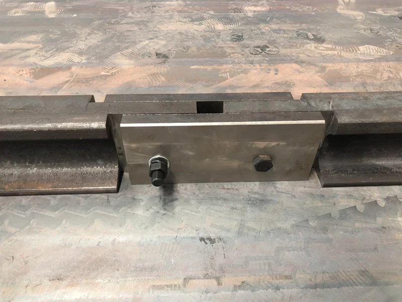
Rail alignment and wheel passage
The rail heads need to form a suitable transition at the joint. Poor alignment or an unsuitable rail-end arrangement can cause impact as crane wheels pass through the joint, contributing to wear on the rail and wheels.
Joint geometry, alignment requirements, and installation tolerances should be reviewed together rather than treated as separate fabrication details.
Coordination with the supporting structure
The rail joint must be coordinated with the movement required at the supporting structure. The designer needs to establish how the rail, its restraints, and the support system interact at that location.
This is why expansion-joint details should be confirmed as part of the project design. They should not be selected solely on the basis of rail size or copied from another runway without checking compatibility.
QU70 Expansion-Joint Example: From Design to Fabrication
A crane rail order for a new workshop in Belarus included four QU70 rail sections requiring special processing at the expansion-joint locations.
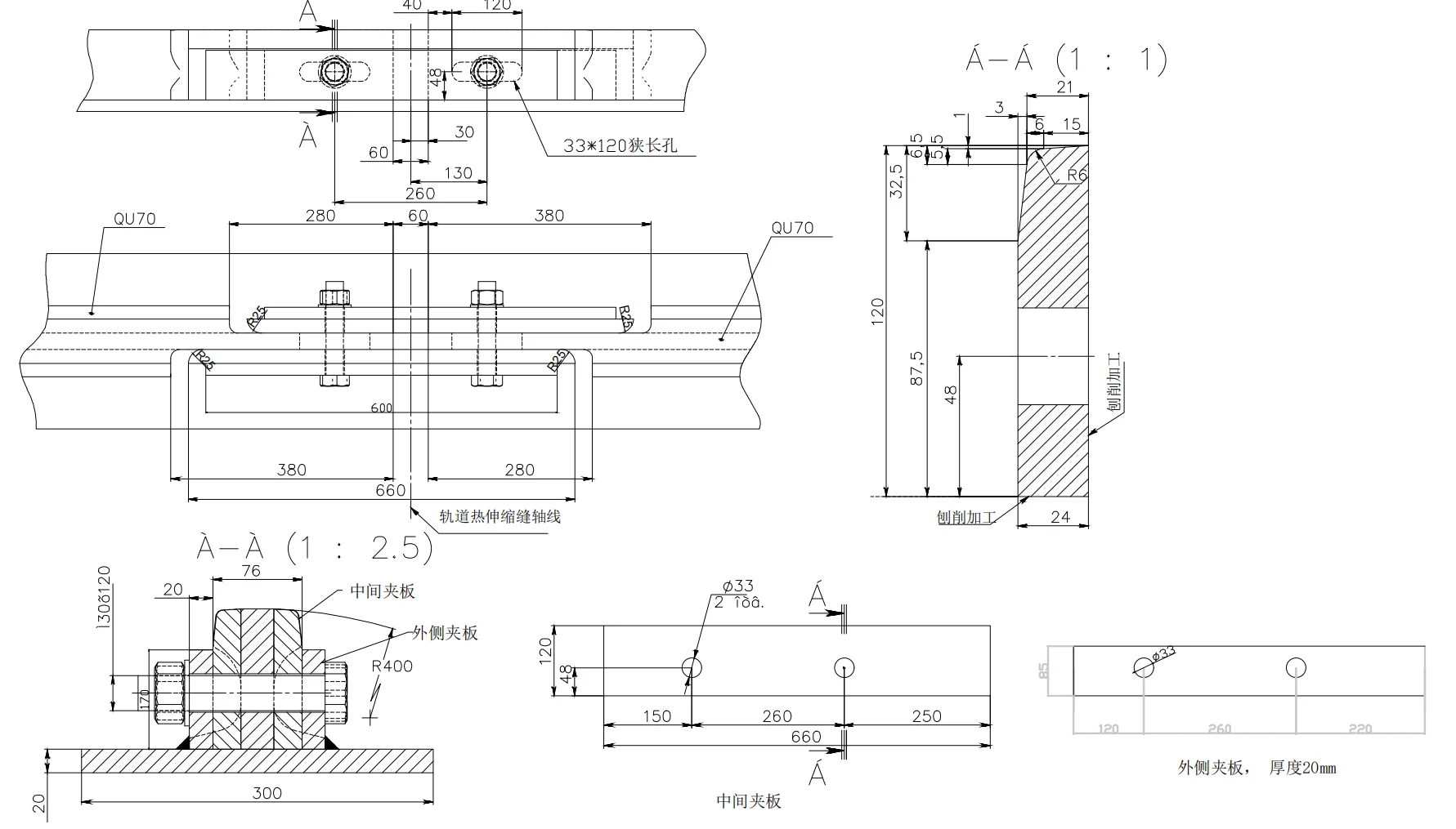
The project drawing defined the joint arrangement, clamp plates, hole patterns, and rail machining details. It also showed how the individual components needed to fit together.
Several dimensions illustrate why the assembly drawing matters. The outer clamp plate was specified as 20 mm thick, the middle plate had a stated overall dimension of 660 mm, and the connection detail included elongated slots measuring 33 × 120 mm.
These are project-specific fabrication dimensions, not general requirements for QU70 expansion joints.
The drawing also showed a 60 mm dimension across the central joint region. Before using this value for fabrication or installation, its dimension lines and reference faces need to be checked. It should not automatically be interpreted as the required expansion gap or the total movement available in service.
The side-machining detail also needs to be read against the relevant view so that the fabricator can identify where the machining applies and what finished geometry is required.
This example highlights an important distinction: the QU70 designation identifies the rail profile, while the approved joint drawing defines the additional geometry and connection details needed for that particular installation.
The wider order also included W116 rail clips, anchor bolts, leveling bolts, and rubber pads. These items formed part of the rail supply, but the material schedule still needed to distinguish the expansion-joint components from the hardware used elsewhere in the rail support system.
What Should You Confirm Before Ordering?
For a crane rail expansion joint, the quotation should be based on the actual project requirements rather than the rail profile alone.
| Item | Information to Confirm |
|---|---|
| Rail specification | Profile, material grade, applicable specification, section lengths, and quantities |
| Joint location | Position of each expansion joint and its relationship to the supporting structure |
| Approved drawings | Latest revision of the assembly drawing, individual part details, and relevant project notes |
| Movement requirements | Required movement allowance, specified joint setting, and reference installation conditions |
| Rail machining | End geometry, machining locations, dimensions, and applicable tolerances |
| Plates and connections | Plate materials and thicknesses, hole patterns, slot dimensions, bolts, and connection arrangement |
| Fastening components | Required rail clips, anchor bolts, leveling bolts, pads, and other items within the supply scope |
| Inspection | Dimensional checks, fit-up requirements, and any specified inspection records |
Two points deserve particular attention before production starts.
First, confirm that the drawing clearly identifies the required movement and the dimensions used to manufacture the joint components. If the gap, reference faces, or machining details are unclear, resolve them before fabrication.
Second, define the supply scope. If rail sections, plates, and fastening components are supplied separately, their interfaces must match the approved design. Check the parts against the same drawing revision to avoid discrepancies between components.
The movement allowance and structural design criteria should be confirmed by the project’s responsible engineer. The supplier can then review the approved drawings to establish the rail, fabrication, and component requirements for quotation.
Request a Quote for Crane Rail Expansion Joints
For a crane rail expansion joint, send Glory Track the latest approved joint drawing and rail schedule. Include the rail profile, quantities, specially processed sections, and required fastening components.
Where the movement allowance or installation setting is specified separately, include those project documents as well.
This allows Glory Track to review the required rail supply and machining work against the project drawings and prepare a quotation based on the defined scope.