
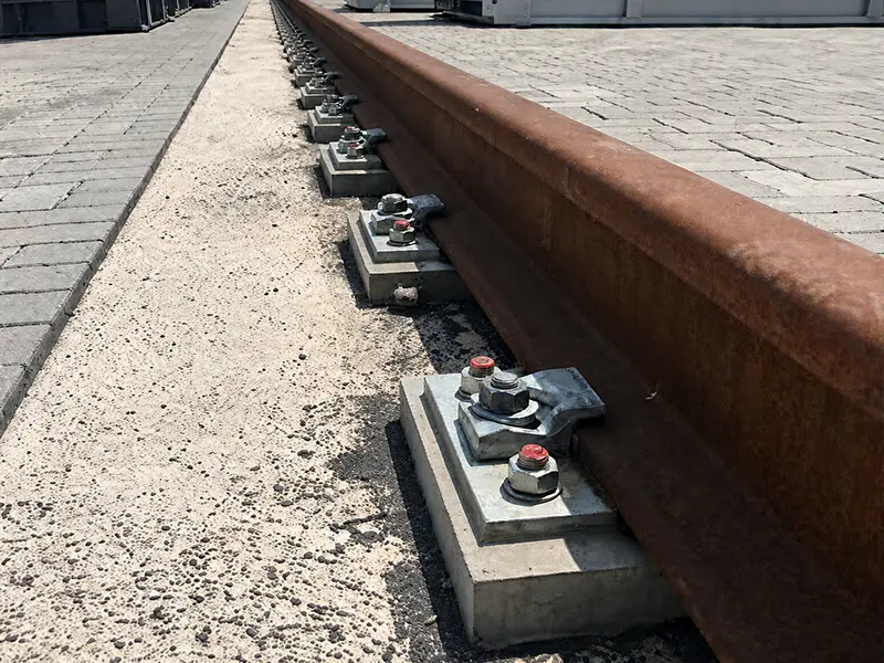
The crane rail clip quantity for a runway depends on the length of each rail line, the specified clip spacing, the number of rail lines, and the fixing details at rail ends, joints, and special sections. Start by counting the fixing positions on each rail line. Then multiply by the number of individual clips required at each position.
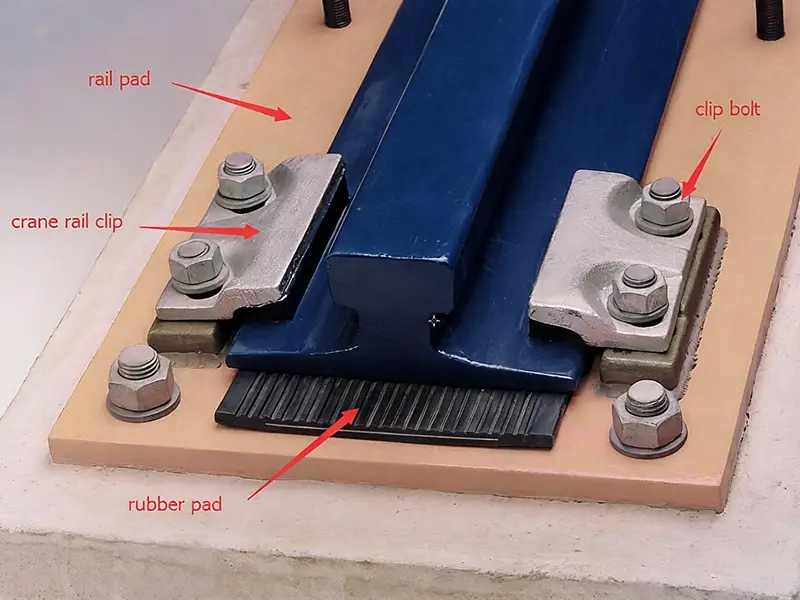
For a layout with one clip on each side of the rail, each fixing position contains two clips. Keep this distinction clear when preparing a material list or requesting a quote.
The calculation below provides a practical way to estimate the quantity. The final count should follow the approved rail fixing drawings.
How Many Crane Rail Clips Does a Runway Need?
There is no single clip quantity that applies to every crane runway. Two runways of the same length can need different quantities if their clip spacing, end details, or fixing arrangements differ.
Before calculating, confirm four items:
- The length of each rail line.
- The number of rail lines.
- The specified spacing between fixing positions.
- The number of individual clips at each position.
Also check whether the drawings show different arrangements at joints or special sections.
Be clear about what “runway length” means. A runway with two rail lines, each 60 m long, contains 120 m of rail. If you use 60 m in the calculation, multiply by two rail lines. If you use the total rail length of 120 m, do not multiply by two again.
How to Calculate Crane Rail Clip Quantity
Understand What You Are Counting
Three terms need to be kept separate:
| Term | Meaning |
|---|---|
| Clip spacing | The distance along the rail between adjacent fixing positions, usually measured center to center. |
| Clip position or pair | One fixing location along the rail. In a paired arrangement, this position contains one clip on each side of the rail. |
| Individual clips | The separate clips counted in the material list and purchase quantity. |
For example, a drawing marked “clips in pairs at 600 mm centers” means one pair at each fixing position—not one individual clip every 600 mm. This type of notation appears in actual crane rail project drawings.
Step 1: Make a Preliminary Estimate
For rail lines with the same length and fixing arrangement, use:
Napprox = L s × R × cWhere:
- = length of one rail line.
- = spacing between fixing positions.
- = number of rail lines.
- = individual clips at each position.
Use the same units for length and spacing. For example, convert 600 mm to 0.6 m when the rail length is in meters.
This formula is useful for an early budget estimate. However, dividing length by spacing gives an approximate number of intervals. It does not fully account for the first and last fixing positions.
Step 2: Account for the End Positions
For a more accurate count, use the distance between the first and last fixing positions.
If the end positions are specified and the intermediate spacing can be adjusted without exceeding the permitted maximum:
P = L − a − b smax +1Where:
- = fixing positions on one rail line.
- = distance from the start of the rail to the first fixing position.
- = distance from the last fixing position to the end of the rail.
- = maximum permitted spacing.
- = round up to the next whole number.
The extra one converts the number of intervals into the number of fixing positions.
Then calculate the individual clips:
Nbase = P × R × cThis method assumes a continuous section with no obstructions or special fixing details. Where drawings already show every clip position, count those positions directly.
Step 3: Work Through an Example
Assume the following layout:
| Item | Example value |
|---|---|
| Length of each rail line | 60 m |
| Number of rail lines | 2 |
| Maximum fixing-position spacing | 600 mm |
| First and last fixing positions | 150 mm from each rail end |
| Individual clips per position | 2 |
First, calculate the distance between the first and last fixing positions:
60 − 0.15 − 0.15 = 59.7 mNext, calculate the positions on one rail line:
P = 59.7 / 0.6 +1 =101Finally, calculate the total individual clips:
Nbase = 101 × 2 × 2 =404The base quantity is 404 individual clips.
The dimensions in this example explain the counting method only. They are not recommended spacing or end-distance requirements for a real runway.
Step 4: Check the Layout Before Ordering
Compare the base quantity with the drawings. Check whether any positions must be added, removed, relocated, or fitted with a different clip type.
If the runway contains sections with different spacing, calculate each section separately. Do not count a shared fixing position twice at the boundary between sections.
Keep spare clips separate from the installed quantity:
Norder = Ninstalled + NsparesAny spare quantity should follow the purchase specification or an agreed project allowance.
How Clip Spacing Affects the Quantity
For the same rail length and fixing arrangement, smaller crane rail clip spacing means more fixing positions and more individual clips.
The following table shows the approximate relationship for a layout with two clips at each position:
| Example spacing | Positions per meter of rail | Individual clips per meter of rail |
|---|---|---|
| 500 mm | 2.00 | 4.00 |
| 600 mm | 1.67 | 3.33 |
| 800 mm | 1.25 | 2.50 |
These figures exclude end-position adjustments and special sections. They illustrate quantity changes; they are not a spacing recommendation.
Clip spacing should come from the project design, not from the preferred purchase quantity. Gantrex notes that spacing is normally determined by the permissible lateral deflection of the rail. Clip size and spacing also help control lateral rail movement and rail pad creep.
A wider spacing may reduce the initial clip count, but it should not be used unless the rail fixing design allows it.
Factors That Change the Final Count
Number and Length of Rail Lines
Calculate each rail line separately if the lengths or fixing arrangements differ. Multiplying one line’s quantity by the number of lines only works when those lines have the same layout.
This matters on projects with extensions, maintenance sections, or separate runway sections.
Rail Ends
The first and last fixing positions affect the number of intervals along the rail. Use the end distances shown on the drawings rather than assuming that a clip sits exactly at each rail end.
Check both ends. Their fixing details may not be identical.
Rail Joints
Check the fixing detail at welded joints, bolted joints, and expansion joints separately. Do not automatically add one pair of clips for every joint.
A joint detail may change clip positions or require a different clip type. For example, special cutout clips may be needed where splice bars are used.
Count the actual arrangement shown in the joint detail.
Curves and Special Load Areas
Curved rail sections, guide-wheel areas, and other special load areas may have different fixing requirements from the rest of the runway. Calculate these sections separately using the spacing and clip arrangement shown on the project drawings.
Where the layout calls for closer spacing or a different clip model, record the quantity for each type separately. Do not apply the standard straight-section spacing to the entire rail line unless the design allows it.
Supply Units and Spare Parts
Make sure the material list distinguishes between:
- Individual complete clips.
- Pairs of clips.
- Separate clip components.
- Spare clips or spare hardware.
A quotation for “200 sets” can be unclear unless the contents of each set are defined. State whether one set means one complete clip assembly or a pair for both sides of the rail.
What Information Is Needed for a Rail Clip Quote?
To request a rail clip quote from Glory Track, send the rail profile, rail lengths, required quantity, and available drawings. Include the clip spacing and fixing method if these have already been specified.
| Information | Details to Include |
|---|---|
| Rail profile | Rail designation and standard, or a dimensioned rail section drawing. |
| Rail length | Length of each rail line and the number of rail lines. |
| Clip layout | Specified spacing, number of clips at each position, and any local changes. |
| Required quantity | Number of individual clips, with spare clips listed separately. |
| Fixing method | Welded-base or bolted fixing requirements. |
| Drawings | Rail layout, supporting structure, and details at rail ends, joints, and special sections. |
| Supply scope | Complete clip assemblies, fixing hardware, or replacement components. |
If available, also include the design loads, rail pad details, and mounting dimensions. These help confirm which clip model fits the application.
If the layout is still being developed, mark the quantity as preliminary and send the available drawings with your inquiry. State the counting unit clearly—for example, “404 individual complete clip assemblies, excluding spares”—so there is no confusion between individual clips, pairs, and sets.