
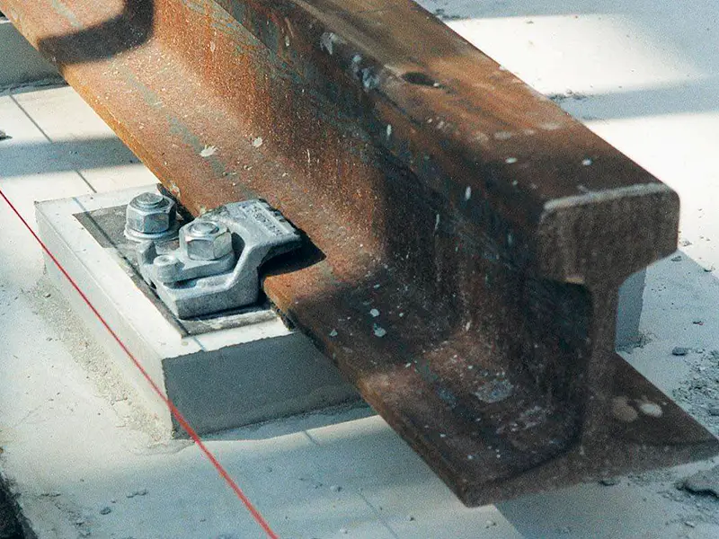
After the crane rail system has been installed and the grout beneath the steel soleplates has fully cured, a survey reveals that the top of a QU100 rail is 3 mm below the specified design elevation.
The rail pads, clips, steel soleplates, and grout are already in place.
Can this height difference be corrected by replacing the existing rubber pad with a thicker one? Or can precision steel shims provide a more controlled adjustment without removing the cured grout?
Rubber rail pads are designed to provide resilient support, distribute wheel loads, and reduce vibration. They are not intended for precise post-installation height correction. Their compression under load makes the actual height increase difficult to predict when a thicker pad is installed.
For small height corrections, precision steel shim sheets may provide a more controlled alternative. Where the fastening system permits, thin steel shims can be installed between the rubber pad and the steel soleplate in selected thickness increments, such as 1 mm or 2 mm.
This approach allows the rail elevation to be adjusted without directly disturbing the cured grout beneath the soleplate. However, the pad bearing condition, rail clip engagement, and allowable vertical adjustment must all be checked before the modification is approved.
1. What Causes a Crane Rail Height Difference?
Using the same QU100 rail profile does not guarantee the same installed rail-top elevation. The final height depends on several components and installation conditions:
- Supporting beam or foundation elevation
- Steel soleplate setting height and flatness
- Rail pad nominal thickness and compression
- Rail section height and seating condition
- Grout bed thickness and bearing condition
A simplified relationship is:
Rail-top elevation = Foundation elevation + Grout thickness + Soleplate thickness + Effective pad thickness + Rail section height
When precision steel shims are added between the rubber pad and soleplate, their thickness should also be included in this relationship.
For example, if a QU100 rail sits 3 mm below its specified design elevation after grouting, the deviation may result from the supporting structure, grout bed, soleplate positioning, pad thickness or compression, or a combination of these factors.
The rail pad should not automatically be identified as the cause. The complete support assembly needs to be checked before any component is replaced or adjusted. For a rail system with fully cured grout, identifying the source of the deviation is particularly important. It helps determine whether a small adjustment using precision steel shims is appropriate or whether another part of the supporting assembly requires attention.
Confirm the Actual 3mm Height Difference
Before choosing a correction method, confirm that the measured 3 mm difference refers to the absolute rail elevation against the project datum.
This is different from the cross-level difference between two parallel rails or local elevation variations along the same rail. These measurements describe different installation conditions and should be evaluated separately.
For this situation, the key measurement is how far the rail top sits below its specified design elevation after the grout has cured. Also check whether the deviation is consistent along the rail or limited to individual support locations.
This distinction helps determine whether a small height correction using precision steel shim sheets is appropriate and where the adjustment may be required.
How Should Rail Elevation Be Measured?
A surveying level or precision optical level can be used to check the rail-top elevation. A practical measurement procedure includes:
- Establish a fixed elevation benchmark based on the project datum.
- Set measurement points at each designated supporting column or support interval.
- Measure the top elevation of each rail along the runway.
- At matching transverse positions, measure both parallel rails to check their relative height difference.
- Record the readings and compare them with the design elevations and applicable tolerances.
Measuring both rails at the same cross-section is important. One rail may appear correctly aligned when checked independently while the opposite rail is actually higher or lower.
Significant elevation differences can affect crane operation and cause uneven wheel-load distribution. Depending on the structural arrangement, excessive deviations may contribute to wheel unloading, crane skewing, or additional structural stresses.
If wheel flange rubbing is also observed, check rail gauge and horizontal alignment separately. A vertical elevation difference alone does not necessarily explain wheel flange contact.
2. Why Rubber Rail Pads Are Not Suitable for Precision Leveling
Rubber rail pads and steel shims serve different functions in a crane rail support system.
Rubber Rail Pads Provide Resilient Support
A rubber rail pad is installed between the crane rail and its steel supporting plate. Its main functions include:
- Distributing wheel loads over a larger supporting area
- Reducing local bearing stress
- Damping vibration and operating noise
- Separating the rail from the steel support to reduce fretting and surface wear
- Allowing limited rail movement and rotation under operating loads
Rubber is an elastic material. When a crane wheel applies a load to the rail, the pad compresses according to its material properties, loading conditions, and support arrangement.
Its working thickness can therefore differ from its nominal thickness. The compression response may also be nonlinear, with different wheel loads producing different compression levels.
For example, a 7 mm rail pad does not guarantee that the installed rail top will be exactly 7 mm higher than the steel soleplate.
This is why replacing the existing pad with a thicker one is not a reliable way to achieve a specific 1 mm, 2 mm, or 3 mm height correction. It may also change the pad’s compression characteristics and affect the fit between the rail foot and fastening clips.
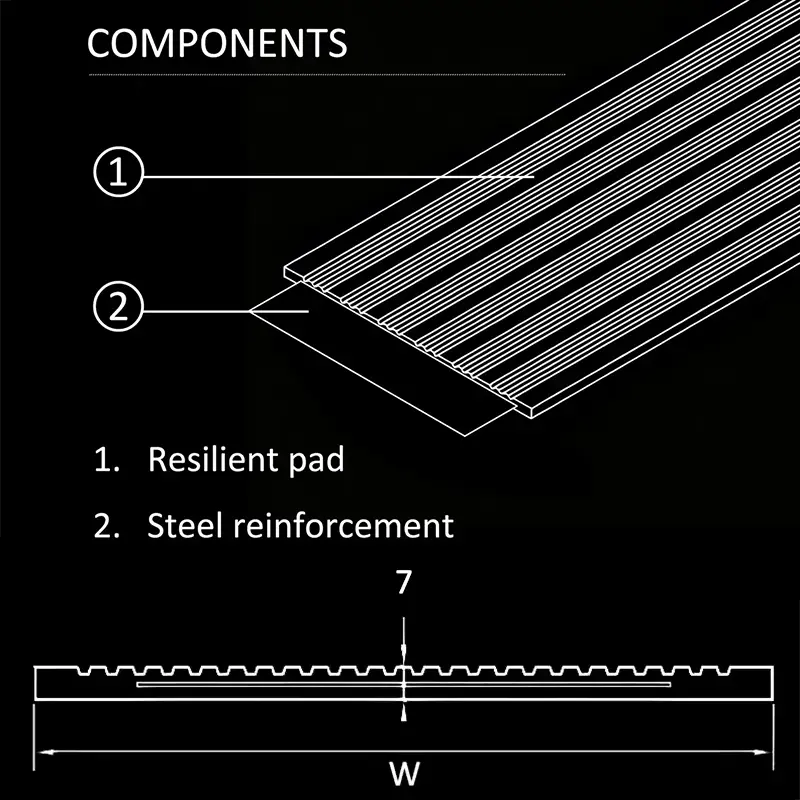
Steel Shims Provide Controlled Height Adjustment
Steel shims have a different purpose. They provide a rigid, measurable thickness for dimensional adjustment and undergo very little compression under their intended service loads.
For small post-grouting height corrections, precision cold-rolled steel shim sheets can provide a more controlled dimensional adjustment while retaining the original rubber pad.
Available in selected thicknesses, such as 1 mm and 2 mm, these sheets can be selected individually or combined, where permitted by the fastening design, to achieve the required nominal adjustment. For example, combining a 1 mm shim sheet with a 2 mm sheet provides a nominal total thickness of 3 mm.
Unlike changing the rubber pad thickness, this method retains the original resilient pad while adding a more predictable rigid thickness beneath it. The actual change in rail elevation must still be verified after installation.
The shim dimensions, bearing coverage, and total thickness must be compatible with the existing rail pad and fastening arrangement. Sufficient clearance must also remain for proper rail clip engagement and rubber nose contact.
Where Should Steel Shims Be Installed for Post-Grouting Height Adjustment?
Once the grout beneath the steel soleplate has fully cured, the original leveling space beneath the soleplate is no longer available for direct shim insertion.
For post-grouting height correction, steel shims must be installed at an adjustment interface permitted by the rail fastening system.
The exact position depends on the system design. Some purpose-designed adjustable crane rail systems use shim plates between upper and lower soleplates to raise the rail after installation. Other fastening arrangements may require a different approved adjustment detail.
Before adding thin steel shim sheets, confirm that the proposed installation position provides adequate bearing support and does not compromise the rubber pad, rail clip engagement, or fastening capacity.
The shim location should always follow the approved fastening system drawing rather than being assumed to be the same for every crane rail installation.
The support assembly can be understood as follows:
| Component | Position and Function |
|---|---|
| Crane rail | Top of the fastening assembly |
| Rubber rail pad | Directly beneath the crane rail |
| Precision steel shim sheets | Between the rubber pad and steel soleplate for height adjustment |
| Steel soleplate | Supports the shim sheets, rubber pad, and rail clips |
| Cured non-shrink grout | Supports the underside of the steel soleplate |
| Concrete foundation | Main supporting structure |
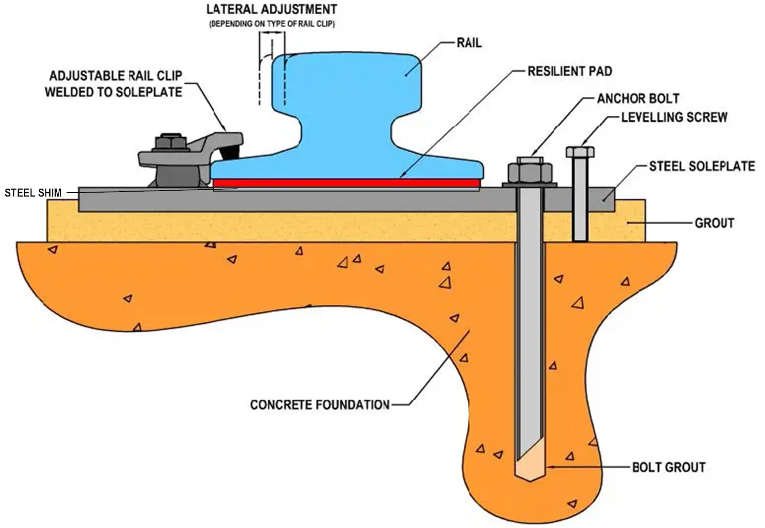
The additional steel shim sheets raise the rail and rubber pad relative to the steel soleplate. Unlike conventional leveling shims beneath the soleplate, this arrangement does not require disturbing the cured grout bedding.
The shim dimensions and coverage must provide adequate bearing support beneath the rubber pad. Their installation must also be compatible with the existing rail fastening design.
Steel Shim Material and Installation Requirements
When precision steel shim sheets are used for post-grouting rail height correction, several details should be considered:
- Material: Use precision cold-rolled steel with a specified material grade and suitable corrosion protection for the installation environment.
- Thickness: Select the shim thickness according to the measured elevation difference. For example, 1 mm and 2 mm sheets can be used individually or combined to provide a nominal 3 mm adjustment.
- Dimensions: Ensure adequate bearing coverage beneath the rubber pad. Avoid narrow or isolated pieces that create concentrated loads or unsupported areas. For continuous rail pad systems, the shim arrangement should maintain the designed bearing support along the adjusted section. Avoid isolated short shim pieces unless specifically permitted by the approved support design.
- Surface condition: Shim sheets should be flat, clean, and free from burrs, deformation, and other surface defects.
- Fastening compatibility: Confirm that the additional thickness does not compromise clip engagement, rubber nose contact, bolt engagement, or the specified rail restraint.
The total shim thickness must remain within the allowable adjustment range of the fastening system. The actual rail elevation should always be verified after installation, rather than determined solely from the nominal shim thickness.
How Does the Adjustment Work?
Once the 3 mm height deviation has been confirmed and the shim arrangement approved, the adjustment involves three main steps.
Step 1 – Release and Support the Rail
Unload and safely support the affected rail section according to the approved installation procedure. Release the relevant rail clips and use an approved lifting method to create sufficient clearance at the rubber pad–soleplate interface.
Step 2 – Install the Steel Shims
Insert the selected precision steel shim sheets between the rubber pad and steel soleplate. Ensure adequate bearing coverage and that the original rubber pad remains properly seated.
Before securing the clips, check that the added shim thickness does not compromise rubber nose contact, clip engagement, or bolt fastening.
Reinstall and secure the rail clips according to the manufacturer’s requirements.
Step 3 – Verify the Adjusted Elevation
Measure the rail-top elevation again against the project datum. Confirm that the required correction has been achieved and that the existing soleplate and cured grout remain properly supported.
Need Help with Your Post-Grouting Crane Rail Height Adjustment?
Correct rail elevation depends on more than the rail profile or pad thickness. The supporting structure, resilient pad, and rail clip configuration must work together.
Glory Track supplies 7 mm MK7 steel-reinforced continuous rail pads and crane rail fastening components for industrial rail systems.
For projects involving rail height differences or pad compatibility, send us your rail profile, measured elevation readings, pad thickness, clip model, and soleplate drawing.
Our team can review the component arrangement and provide a suitable product recommendation and quotation.
Contact Glory Track to discuss your crane rail system requirements.