
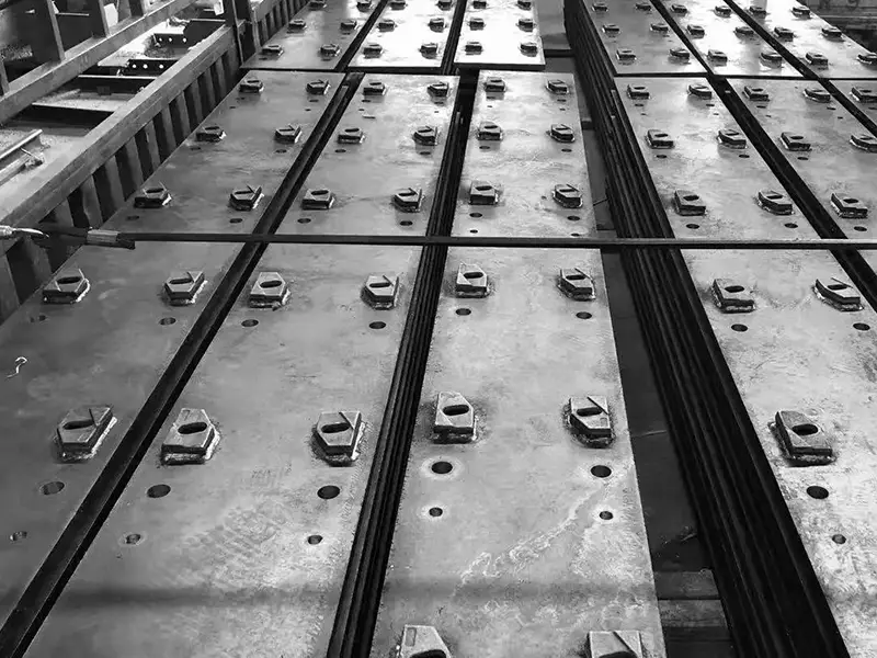
One customer recently asked us: “If the rail clip bases are welded to the steel soleplates before delivery, how are the soleplates aligned on site when the anchor-hole positions are already fixed?”
This guide addresses that practical question for a crane rail installation on a concrete foundation with grout support. The key is to distinguish the factory-set clip-base layout from the final position of the soleplates and rails on site. The approved project drawings and the selected clip’s installation instructions govern the actual installation sequence and acceptance requirements.
What Is Fixed by Pre-Welding—and What Can Still Be Adjusted?
There are three separate positioning tasks in this arrangement:
| Relationship | How the position is established |
|---|---|
| Clip base to soleplate | Set during factory welding according to the approved layout |
| Soleplate to foundation | Adjusted on site using survey references and the specified levelling arrangement |
| Rail to clip assembly | Adjusted on site within the selected clip’s permitted range |
The factory establishes the clip-base layout on each plate. The site team establishes the final position of the plates and rails.
Before installation, check the supplied soleplates against the approved drawing. Confirm the rail profile, clip model, anchor-hole pattern and base orientation.
These details must be coordinated before manufacture. Continuous soleplate systems require planning across design, fabrication and installation, rather than treating each stage as an isolated task.
Step 1: Establish the Rail Centreline and Check the Anchors
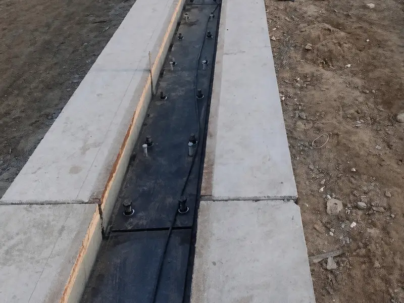
Start with the project survey references, not the outside edges of the steel plates.
Identify the intended rail centreline and reference elevations. Compare the actual foundation and anchor positions with the approved layout drawing.
Before positioning the plates, check that:
- The anchor arrangement matches the soleplate hole pattern.
- Each plate can reach its intended position.
- Plate identification and orientation match the layout.
- Any discrepancy has been reviewed before securing the plate.
A correctly manufactured soleplate may still encounter an incorrectly positioned anchor. Pre-welding does not remove the need to verify site conditions.
Confirm the acceptance tolerances for crane rail soleplate alignment before installation begins. Use the approved project requirements for survey checks and inspection records. Specialist rail installation guidance likewise emphasises agreed tolerances and geometrical alignment.
Step 2: Set the Horizontal Position for Crane Rail Soleplate Alignment
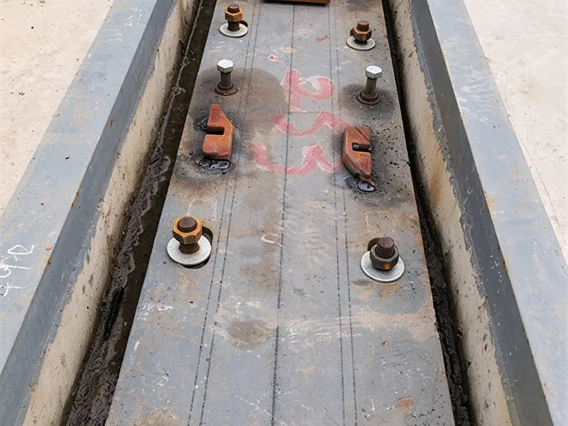
Place the soleplates in the sequence shown on the approved drawing.
Use suitable survey equipment and the project’s setting-out method to adjust their horizontal positions. Follow the intended rail centreline and its relationship to the pre-welded bases.
Do not rely only on whether adjacent plate edges appear straight. The plate edge is not a substitute for the specified survey reference.
As each section is positioned, check its relationship with the sections on either side. Confirm the plate orientation, the specified section gaps and the continuity of the planned clip-base arrangement.
At this stage, the task is to position the supporting plates. Final crane rail alignment comes after the rail is placed.
Step 3: Complete Soleplate Levelling Before Grouting
After establishing the horizontal position, adjust the plates to the required elevation using the specified levelling arrangement.
Where the design uses levelling screws, these provide height adjustment before grouting. Their location and use must follow the approved soleplate details.
Check elevations along the installation rather than adjusting each plate in isolation. For a paired-rail runway, also check the required relationship between the two rail lines.
Before releasing the plates for grouting, verify:
| Check | What to confirm |
|---|---|
| Horizontal position | The plates follow the intended rail line |
| Elevation | Each section meets the specified level |
| Adjacent sections | Plate positions and gaps match the layout |
| Anchors | The installed arrangement is compatible with the holes |
| Welded bases | Their positions and orientation match the approved drawing |
Crane rail soleplate alignment must be checked before grouting. Correct plate position and elevation provide the starting point for rail alignment, but they do not guarantee the final rail geometry.
Step 4: Complete the Grout Support Without Losing Alignment
After the required checks, complete the grout installation according to the approved method.
The grout supports the soleplate from below. Both position and support matter: a plate at the correct elevation still needs the specified bearing condition beneath it. Soleplate system guidance emphasises complete grout support without voids.
The installation method should define:
- How the plates are held in position during grouting.
- Surface preparation and grout placement requirements.
- Curing and strength requirements.
- When subsequent tightening or loading may proceed.
Do not assume that the installation is ready for loading simply because the grout surface appears hard.
Some projects include trial positioning of the rails before grouting. Others install the rails after the grouted support is ready. Follow the approved sequence for the selected system.
The objective is to preserve the established plate position while completing the support beneath it.
Step 5: Align the Rail Within the Pre-Welded Clip Bases
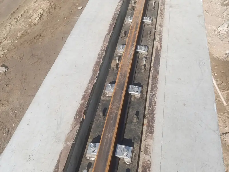
Once crane rail soleplate alignment has been checked and the supporting arrangement is ready, install the specified rail pad, where required. Then place the rail between the clip bases.
Now check the rail itself against the project survey references. Do not accept its position solely because the soleplates have already been checked.
The adjustable upper components of weldable rail clips allow lateral positioning within the selected model’s permitted range. This is why rail alignment remains possible after the lower bases have been welded.
During adjustment:
- Check the rail’s horizontal position against the intended centreline.
- Adjust its lateral position within the permitted clip range.
- Check the rail elevation and the required relationship between parallel rails.
- Recheck the geometry before final tightening.
The clip’s adjustment range is a defined installation allowance. It is not a way to compensate for unlimited errors in anchor placement, soleplate positioning or welded-base location.
If the rail cannot reach its required position, investigate the cause. Review the survey results, plate positions, base layout and selected components before proceeding.
Step 6: Tighten the Clips and Complete the Final Survey
Where the installation procedure permits, upper clip components may be fitted temporarily during adjustment. Complete final tightening after the required rail position has been confirmed.
Use the instructions for the actual clip model. Tightening requirements, component positions and coating restrictions on mating surfaces can differ between products.
The final inspection should cover:
| Item | Purpose |
|---|---|
| Rail position and elevation | Confirm that the running rail meets the approved geometry |
| Parallel-rail relationship | Confirm the specified gauge and related geometrical requirements |
| Soleplate support | Confirm the required supporting condition |
| Anchors and clips | Confirm correct assembly and final tightening |
| Survey and inspection records | Document the accepted installation condition |
Assess the completed installation against the project’s agreed tolerances. Do not apply a generic alignment limit taken from an unrelated rail system.
Pre-Welding Does Not Replace Site Alignment
Successful crane rail soleplate alignment depends on coordinated factory dimensions and site survey references. Pre-welding establishes the clip-base positions on the plate. Site work establishes the final position of the plates and rails.
Position and level the soleplates first. Then check and adjust the rails within the selected clip system’s limits.
For a project-specific supply review, provide the rail profile, clip model, soleplate drawing and anchor layout. These documents allow the proposed assembly to be checked against the intended installation arrangement.
FAQs About Crane Rail Soleplate Installation
1. What to Do If Anchor Bolts Do Not Align with the Soleplate Holes
The correct action depends on anchor type and the magnitude of misalignment.
Post-installed chemical anchors:
If anchors are not yet installed, first position and level the soleplate using approved survey references. Transfer the hole layout from the aligned soleplate to the foundation, verify rebar location, anchor spacing, edge distance and concrete condition, then drill and install anchors strictly per the approved design and the anchor manufacturer’s instructions.
Cast-in anchor bolts:
Compare actual bolt positions with the approved anchor layout and soleplate drawings. If the deviation is within the designed hole clearance and the soleplate can still meet specified alignment, install it within the permitted adjustment range.
If bolts fall outside the available clearance, use an engineered remedy only: enlarged/slotted holes with suitable heavy plate washers, supplemental anchors under an approved repair design, or a replacement soleplate. The choice depends on deviation, anchor capacity, plate geometry and foundation condition.
Do not flame-cut holes, bend cast-in bolts, or modify welded clip bases without approval from the engineer of record. Document the deviation, obtain the remedy design, re-verify alignment against approved drawings, then tighten anchors and proceed with grouting.
2. How should soleplate flatness be checked after clip-base welding?
Check flatness after clip-base welding, and again while the plate is temporarily supported before grouting. Use a straightedge, feeler gauges, precision level or laser instrument at the measurement points defined in the approved drawings. Welding heat can distort the plate, so visual inspection of the welded bases is not sufficient. Apply the flatness limits stated in the project specification; if none are given, obtain written clarification from the engineer of record or rail-system supplier before proceeding. Re-verify after grouting.
3. Can pre-welded rail clip bases be repositioned on site?
No, not as a routine alignment step. First determine whether the deviation comes from soleplate position, anchor layout, base orientation or shop fabrication dimensions. Cutting, relocating or re-welding bases is a structural repair: it requires engineer approval, an approved WPS, qualified welders and post-weld NDE. After repair, verify base position, weld quality and any plate distortion before continuing. The adjustable range of the clip itself only absorbs minor installation tolerance, not foundational misplacement.
4. Can a crane rail soleplate be realigned after the grout has hardened?
Do not assume the plate can still be moved by its original levelling screws or shims. Once grout has cured, the soleplate, anchors and grout bed act as one supported assembly. Forcing it can crack the grout, disturb anchors or damage the foundation. The responsible engineer must assess the deviation and issue an approved repair method—typically lift, remove failed grout, restore bearing, re-bed with compatible non-shrink grout, then re-survey. Do not cut anchors, break the grout support or re-drill without that approved plan.