
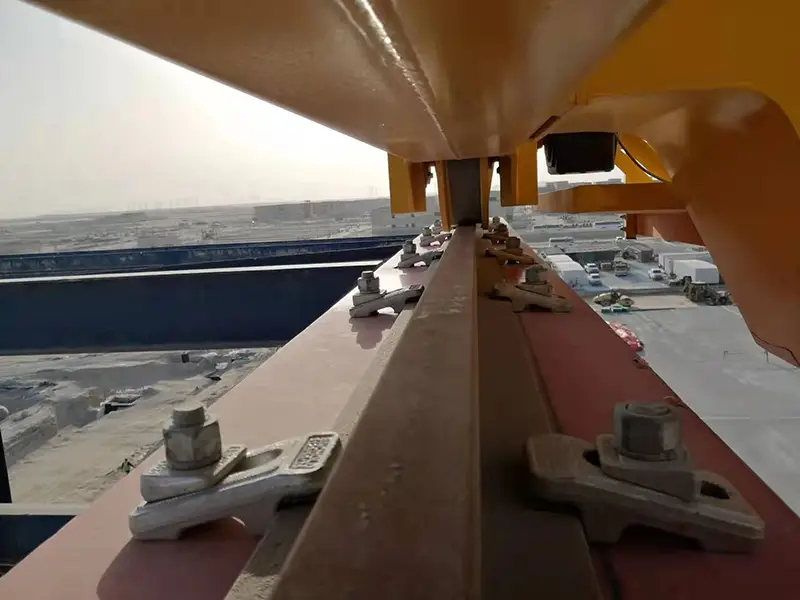
A few millimeters of misalignment between two crane rails can mean the difference between 20 years of smooth operation and chronic wheel wear, structural fatigue, and unplanned shutdowns. This guide explains the critical alignment parameters defined by international standards — and what every project engineer needs to verify before commissioning.
When you invest in crane rails for a port, mine, or industrial facility, the quality of the rail itself is only half the equation. The other half — equally critical to long-term performance — is how precisely those rails are installed. Even the highest-grade DIN 536 crane rail will underperform if crane rail installation tolerance is not met.
This guide covers the key alignment parameters defined by three widely referenced international standards — ISO 12488-1, BS 466, and GB/T 10183 — along with practical guidance on measurement methods, best practices, and how to ensure your installation meets spec from day one.
Why Crane Rail Installation Tolerance Matters
Consider a 20-tonne overhead crane running on a 20-meter span. Every time the crane traverses the runway, its wheels exert significant vertical and lateral forces at the wheel-rail interface. When rail alignment deviates by even 3–5 mm at a single point, the consequences compound over time:
- Accelerated rail head wear — localized contact pressure increases wear rates significantly at misaligned points
- Premature wheel flange thinning — wheels require replacement far sooner than their designed service life
- Increased energy consumption — misalignment raises rolling resistance, drawing higher motor current
- Structural fatigue — loose clips, cracked runway beams, and bolt loosening from dynamic impact loads
- Noise and vibration — audible clicking, grinding, and structural resonance that signals underlying alignment problems
Research on bridge crane rail and wheel wear has shown that incorrect geometry of the crane guiding structure — including rail misalignment — is a primary cause of excessive, uneven wear on both rails and wheels. At busy ports or steel mills where crane downtime represents significant lost throughput, the cost of a single prolonged shutdown often exceeds the entire cost of a professional rail alignment survey. Precision at installation is not a luxury; it is an investment that pays for itself many times over.
The Three Key Standards Explained
Different regions and industries reference different standards for crane runway tolerance. Understanding which standard applies to your project is the first step in defining tolerance requirements.
ISO 12488-1:2012 — The International Reference
ISO 12488-1:2012 (Cranes — Tolerances for wheels and travel and traversing tracks — Part 1: General) is the most widely adopted international standard for crane runway tolerances. It defines four tolerance classes (Class 1 through Class 4), allowing projects to select the precision level appropriate for their application:
- Class 1: Highest precision — for high-speed, automated, or very heavy-duty cranes
- Class 2: Standard precision — for typical overhead and gantry cranes (most commonly applied)
- Class 3: Reduced precision — for light-duty or low-speed applications
- Class 4: Minimal precision — for manual or very light cranes
Most port crane, mining, and heavy industrial applications use Class 1 or Class 2 tolerances. The values cited in this article for ISO 12488-1 are based on Class 2 unless otherwise noted.
BS 466 — The British Standard
BS 466 (Specification for power-driven overhead travelling cranes, semi-goliath cranes, etc.) is commonly referenced in the UK, Commonwealth countries, and regions with British engineering heritage. BS 466 specifies stricter span tolerances than ISO 12488-1 for shorter spans (≤12 m), making it the preferred standard for compact, high-precision crane installations. Note that BS 466 was formally withdrawn and superseded by BS EN 13001, but many projects and specifications still reference it.
GB/T 10183 — The Chinese National Standard
GB/T 10183 (Bridge and gantry cranes — Manufacturing and track installation tolerances) is the Chinese national standard for crane rail installation. The 2005 version is widely referenced in practice, though a 2018 revision (GB/T 10183-2018) also exists with some updated parameters. Key provisions of GB/T 10183-2005 include:
- Span tolerance for spans over 10 m: ±[3 + 0.25 × (S − 10)] mm, maximum ±15 mm
- Elevation difference between two main crane rails in the same cross-section: ≤10 mm (Section 5.2)
- Track centerline position deviation from design axis: ±5 mm (for concrete support structures)
- Rail joint height difference and lateral offset: ≤1 mm each
Important distinction: GB/T 10183 also contains a separate set of elevation tolerance formulas for trolley rails (the small rails on the crane bridge that carry the trolley hoist), found in Section 4.5. These trolley rail formulas — involving trolley gauge K — should not be confused with or applied to the main crane runway rails. The main rail elevation limit is simply ≤10 mm.
For projects sourcing rails from China — which represents a significant share of global crane rail supply — understanding GB/T 10183 alongside ISO 12488-1 and other standards ensures alignment between manufacturing and installation expectations.
The Critical Crane Rail Installation Tolerance Parameters
Regardless of which standard you follow, several key parameters define whether your crane rail installation will perform as designed. Here’s what each one means and what the numbers say.
1. Span (Gauge) Tolerance
The span is the horizontal distance between the center lines of the two running rails. It must match the crane’s design wheelbase within tight limits.
| Standard | Span Range | Tolerance |
|---|---|---|
| ISO 12488-1:2012 | S ≤ 16 m | ±5 mm |
| ISO 12488-1:2012 | S > 16 m | ±[5 + 0.25 × (S − 16)] mm, max ±15 mm |
| BS 466 | S ≤ 12 m | ±3 mm |
| BS 466 | S > 12 m | ±[3 + 0.25 × (S − 12)] mm |
| GB/T 10183-2005 | S ≤ 10 m | ±3 mm |
| GB/T 10183-2005 | S > 10 m | ±[3 + 0.25 × (S − 10)] mm, max ±15 mm |
| CMAA Spec 74 (US) | All spans | ±6 mm (±1/4 inch) |
Practical example: For a 20-meter span crane:
- ISO 12488-1: ±[5 + 0.25 × (20 − 16)] = ±6 mm
- BS 466: ±[3 + 0.25 × (20 − 12)] = ±5 mm
- GB/T 10183: ±[3 + 0.25 × (20 − 10)] = ±5.5 mm
The span tolerance is measured at every point along the entire runway length — not just at the endpoints. Rails that bow inward or outward beyond these limits cause the crane wheels to bind or, in extreme cases, derail.
2. Horizontal Straightness (Lateral Alignment)
Each rail must be straight in the horizontal plane. ISO 12488-1:2012 specifies two levels of control:
- Local tolerance: ≤ 1 mm per 2 m (measured over a 2000 mm test length at each point along the rail head)
- Total bay length: ≤ 10 mm deviation from the reference datum line over the full runway
The local tolerance (1 mm per 2 m) catches sharp deviations that might otherwise hide within an acceptable total. For example, a 3 mm kink over a 2-meter section near a rail joint would fail the local check even if the total bay deviation is under 10 mm.
This parameter is particularly important at rail joints — whether bolted or welded — where alignment continuity must be maintained across the connection. GB/T 10183 specifies similar local straightness control.
3. Vertical Alignment (Elevation Tolerance)
Both rails must sit at the same elevation to prevent the crane bridge from twisting under load. ISO 12488-1:2012 specifies:
- Elevation difference between opposite rails: E = ±S mm (where S is the span in meters), capped at a maximum of ±10 mm
For example: on a 5 m span, the allowed elevation difference is ±5 mm; on a 15 m span, it is ±10 mm (capped). This means the tolerance scales with span but is limited to 10 mm absolute maximum.
GB/T 10183-2005 Section 5.2 specifies that the elevation difference between two main crane rails in the same cross-section shall not exceed 10 mm for bridge cranes. For gantry cranes, the requirement is stricter at ≤5 mm.
ISO 12488-1 also specifies a local height straightness tolerance: ≤ 2 mm per 2 m (2000 mm test length) along each individual rail. This controls gradual vertical deviation along a single rail, separate from the cross-rail elevation difference.
Even a 5 mm elevation difference causes the crane bridge to tilt under load, transferring lateral forces to the rail flanges and accelerating wear on motors, gearboxes, and wheel bearings.
4. Rail End Step (Vertical Offset at Joints)
At every rail joint where two rail sections meet, the vertical step and horizontal offset between them must be minimized. Industry practice and multiple standards converge on a common benchmark:
- Maximum vertical step at joint: ≤ 1 mm
- Maximum horizontal offset at joint: ≤ 1 mm
Standard status note: ISO 12488-1:2012 addresses rail joint tolerances in Table 6 (“Construction tolerances for rail joints”), with values in the 1 mm range for Class 2. GB/T 10183-2005 specifies that joint height difference and lateral offset shall not exceed 1 mm. BS 466 does not explicitly state a numeric “1 mm” value for joint step in the standard text itself, but engineering practice follows the same convention. The “≤1 mm” figure used across the industry is therefore a convergence of standard requirements and established practice — not a direct verbatim quote from every standard.
Any step exceeding 1 mm creates an impact load every time a crane wheel crosses the joint. For a high-cycle crane making hundreds of crossings per day, this generates dynamic forces that can significantly exceed the static design load, leading to:
- Rail head battering and mushrooming at joints
- Rail spalling at the joint ends
- Cracked or loosened fish plates
- Premature wheel surface damage
If a step is detected after installation, the standard remedy is to grind the transition smooth or — for heavy-duty applications — weld the joint using an aluminothermic welding kit to create a continuous running surface. Welded rail joints eliminate the step and gap issues entirely, which is why many modern crane runway specifications call for continuous welded rail (CWR).
5. Rail End Gap (Thermal Expansion)
Thermal expansion requires a controlled gap between rail ends — unless the rails are continuous welded rail (CWR), which manages thermal forces through the fastening system.
The coefficient of linear thermal expansion for rail steel is approximately 12 × 10⁻⁶ /°C. This means a 12 m rail experiencing a 40°C temperature swing will expand or contract by:
ΔL = L₀ × α × ΔT = 12,000 mm × 12 × 10⁻⁶ /°C × 40°C ≈ 5.8 mm
The correct expansion gap depends on three factors:
- Rail length: Longer rails require larger gaps. A 6 m rail needs roughly half the gap of a 12 m rail under the same temperature range.
- Local temperature range: The gap must accommodate the full seasonal temperature swing at the installation site, not just the temperature on installation day.
- Installation temperature: The gap is set at installation temperature and must be calculated so that rails neither buckle at maximum temperature nor leave an excessive gap at minimum temperature.
For reference, a 12 m rail installed at 20°C in a climate with a temperature range of −10°C to +40°C typically requires a gap of approximately 4–6 mm. Always calculate the specific gap for your project conditions rather than using a generic default.
International Standards Comparison at a Glance
| Parameter | ISO 12488-1:2012 (Class 2) | BS 466 | GB/T 10183-2005 | CMAA 74 (US) |
|---|---|---|---|---|
| Span tolerance (short span) | ±5 mm (S≤16m) | ±3 mm (S≤12m) | ±3 mm (S≤10m) | ±6 mm (all) |
| Span tolerance (long span) | ±[5+0.25(S−16)] | ±[3+0.25(S−12)] | ±[3+0.25(S−10)] | ±6 mm (all) |
| Max span tolerance | ±15 mm | Not explicitly capped | ±15 mm | ±6 mm |
| Local horizontal straightness | ≤1 mm / 2 m | Similar convention | ≤1 mm / 2 m | ≈1 mm / m (1/8″ per 10′) |
| Total bay straightness | ≤10 mm | ≤10 mm | ≤10 mm | — |
| Elevation difference (cross-rail) | ±S mm, max ±10 mm | ≤10 mm | ≤10 mm (≤5 mm for gantry) | ≈10 mm (3/8″) |
| Local height straightness | ≤2 mm / 2 m | — | — | — |
| Rail end step (joint) | ~1 mm (Table 6, Class 2) | Industry convention ≤1 mm | ≤1 mm (explicit) | ≈0.8 mm (1/32″) |
| Expansion gap | Per thermal calculation | Per thermal calculation | Per thermal calculation | Per thermal calculation |
Note: Values marked as “industry convention” or “industry reference” are widely cited in engineering practice and secondary sources but may not appear as explicit numeric values in the standard text itself. Always consult the current standard document for contractual requirements. The “—” entries indicate parameters not separately specified or not verified from primary sources for that standard.
How to Measure Crane Rail Alignment
Accurate measurement requires the right tools and a systematic approach. Professional alignment surveys typically use the following equipment:
| Measurement Tool | Used For | Typical Precision |
|---|---|---|
| Total station or laser tracker | Overall bay alignment and span measurement | Sub-millimeter over long distances |
| Precision optical level | Elevation checks across the runway | Sub-millimeter per setup |
| Dial gauge + straight edge (2 m) | Local straightness at joints (2 m test length) | 0.01 mm resolution |
| Calibrated steel tape (with tension correction) | Span measurement at multiple points | ±1 mm per 20 m (with correction) |
| Rail profile gauge | Rail head wear and profile assessment | Sub-millimeter |
| Tensioned wire (piano wire) | Longitudinal straightness reference line | ~1 mm over 30 m |
ISO 12488-1:2012 notes that when measuring crane tracks, calibrated steel measuring tapes should be used, and readings should be corrected for tape sag and temperature variation. All track measurements for a particular crane should be made with the same measuring tape and the same applied tension force.
When to Measure
Alignment verification should occur at four key project milestones:
- Before installation: Verify the runway beam or concrete support surface meets design flatness and elevation tolerances. If the support is out of spec, the rails cannot compensate — fix the foundation first.
- After rail installation: Measure all parameters before crane commissioning. This is the acceptance survey that confirms the installation meets the specified standard.
- After grouting and clip torque-up: Re-verify critical parameters after the final fixing system is tightened. Grout shrinkage and clip tensioning can shift rails.
- Annually during service: Monitor for creep, settlement, and wear. Early detection of alignment drift prevents cascading damage.
Best Practices for Meeting Tolerance Requirements
Meeting crane rail installation tolerance requirements is achievable with proper planning, the right components, and professional installation practices. Here are the key strategies that consistently deliver results:
1. Specify the Standard in Your Procurement Contract
Don’t leave alignment tolerances to interpretation. Reference the specific standard — ISO 12488-1, BS 466, or GB/T 10183 — and the tolerance class directly in your procurement documents. This ensures that both the rail supplier and the installation contractor work to the same benchmark.
2. Use Adjustable Rail Clips
Forged rail clips with shim adjustment allow fine correction after installation. Shim plates let installers dial in the final alignment with precision — something fixed welded clips cannot achieve. For most crane rail applications, adjustable clips are worth the modest additional cost.
3. Ensure Proper Rail Support Preparation
The rail support surface — whether a steel girder or concrete beam — must be flat, level, and properly prepared before rail installation. Key checks include surface flatness, centerline position, and elevation conformity to the design documents.Steel soleplates provide a precision machined interface between the rail and the support structure, simplifying alignment.
4. Grout the Rail Base Properly
Full-contact grouting under the rail base (using non-shrink cementitious grout or epoxy grout) prevents settlement and movement. Proper grouting ensures the load is distributed evenly and the rail stays where it was set. Rail pads also play a critical role in load distribution and vibration damping.
5. Install Expansion Joints Correctly
Position expansion joints at beam ends or structurally appropriate locations. Calculate the gap based on the local temperature range and rail length — not a generic default. For regions with extreme temperature swings, the gap calculation becomes particularly critical.
6. Consider Welded Joints for Heavy-Duty Applications
For high-cycle, heavy-duty crane operations — such as port crane runways — continuous welded rail (CWR) eliminates the step and gap issues at joints entirely. While welding adds cost and requires specialized welding and heat treatment procedures, the payoff in reduced maintenance and extended rail life is significant for demanding applications.
How Your Rail Supplier Supports Proper Installation
A professional rail supplier’s role extends beyond delivering rails that meet dimensional and material specifications. The right supply partner actively supports the installation process in several ways:
Pre-Installation Technical Support
- Rail section selection guidance — matching the rail profile and steel grade to your crane’s wheel loads, duty cycle, and environmental conditions
- Fastening system recommendations — specifying the appropriate fastening system, clip type, pad thickness, and bolt grade for your support structure
- Joint design consultation — advising whether bolted joints, welded joints, or a combination is optimal for your application
- Thermal gap calculation — providing installation-temperature-specific gap values based on your project location and rail length
Delivery in Installation-Ready Condition
- Rails delivered with machined joint ends and correct bevel geometry for welding or bolted connection
- Pre-drilled holes (where specified) positioned within tolerance for clip installation
- Rail lifting clamps provided or recommended for safe unloading and placement
- Full material documentation (MTC per EN 10204) for project records and compliance verification
Post-Delivery Support
- Technical drawings and installation guidelines provided with the shipment
- Engineering support available during the installation phase for any field questions
- Alignment verification guidance — including recommended measurement methods and acceptance criteria
- Spare parts and replacement components available for long-term maintenance
When you choose a supplier who provides this level of technical partnership — backed by complete crane rail system solutions and custom rail processing services — the crane rail installation tolerance requirements become a collaborative effort rather than a solitary burden on the installation contractor. The rails arrive right, the guidance is clear, and the installation has the support it needs to meet spec.
Conclusion
Crane rail installation tolerance is not just a specification on paper — it is the engineering foundation of safe, reliable, and long-lasting crane operation. The critical parameters — span, horizontal straightness, vertical elevation, rail end step, and expansion gap — are defined by international standards including ISO 12488-1, BS 466, GB/T 10183, and CMAA 74. While each standard uses slightly different formulas and values, they all converge on the same principle: precision at installation is non-negotiable.
For project engineers and procurement managers, the key takeaways are:
- Verify all parameters after installation, before crane commissioning
- Use adjustable fastening systems that allow fine alignment correction
- Work with a supply partner who provides technical support, not just steel
- Conduct annual alignment surveys to catch drift before it causes damage
At Glory Track, we supply certified crane rail systems with full technical documentation, installation guidance, and engineering support. Our rails meet international standards including EN 13674, AREMA, and GB/T — and our team provides the technical partnership you need to achieve a precision installation. Contact our engineering team to discuss your crane rail project requirements.