
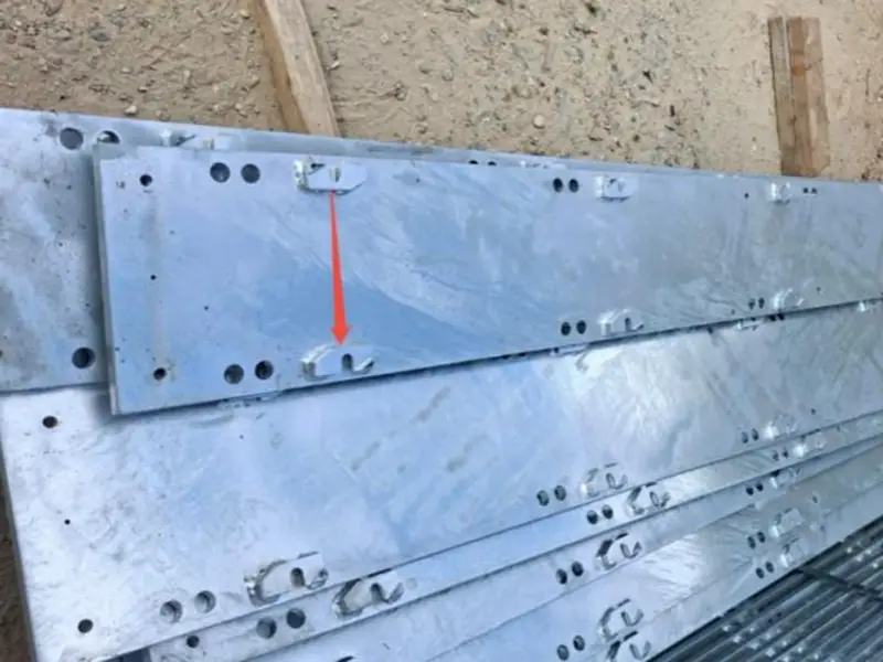
An existing stock of hot-dip galvanized steel soleplates was originally fitted with welded rail clip bases for A100 crane rails. These soleplates are now intended for a new project using QU80 or QU100 rails. The plates themselves are still in good condition, but the existing clip base positions do not match the requirements of the new rail profiles. Can these soleplates be modified for reuse? What is the safest and most cost-effective way to adapt them?
This article outlines Glory Track’s approach to assessing and modifying existing stock soleplates for a different rail profile. It covers the evaluation process, three practical modification options, and answers to common questions from customers.
A100 vs. QU80 and QU100: Key Dimensional Differences
| Rail Profile | Standard | Head Width (mm) | Rail Height (mm) | Base Width (mm) | Theoretical Weight (kg/m) |
|---|---|---|---|---|---|
| A100 | DIN 536 P1:1991 | 100 | 95 | 200 | 74.30 |
| QU100 | YB/T 5055-2025 | 100 | 150 | 150 | 89.05 |
| QU80 | YB/T 5055-2025 | 80 | 130 | 130 | 64.41 |
Differences in head width and rail height mainly affect wheel-to-rail compatibility and the installation requirements of the overall rail system. They are not the primary dimensions to consider when evaluating the lateral fit of the existing soleplates. For this modification, the key dimension is the rail base width: A100 has a base width of 200 mm, compared with 150 mm for QU100 and 130 mm for QU80.
This leads to the first conclusion: the existing soleplates, originally designed for A100 rails, are generally wider than necessary for the narrower QU rail profiles. The soleplate itself is usually wide enough to accommodate the new rails. The main issue is not the soleplate width, but the existing welded rail clip bases, which were positioned specifically for the A100 rail profile and may not align with the new rail profiles.
W120 Installation Dimensions: Why the Clip Bases Need to Be Repositioned
The W120 is a welded-base rail clip from Glory Track. Each W120 assembly consists of one welded base and one adjustable top clip.The same W120/21 series can accommodate A100, QU80, and QU100 crane rails, with the appropriate configuration selected for use with or without rail pads.
This compatibility is based on installation dimensions that vary with the rail base width. When the rail profile changes, the spacing between the welded bases must also change. The adjustable upper section then fits the corresponding rail base.
There are three key installation dimensions:
- V – Distance between the two welded bases installed on opposite sides of the rail = Rail base width + 22 mm
- W – Minimum assembly width = Rail base width + 120 mm
- U – Maximum width of the adjustable upper section = Rail base width + 162 mm
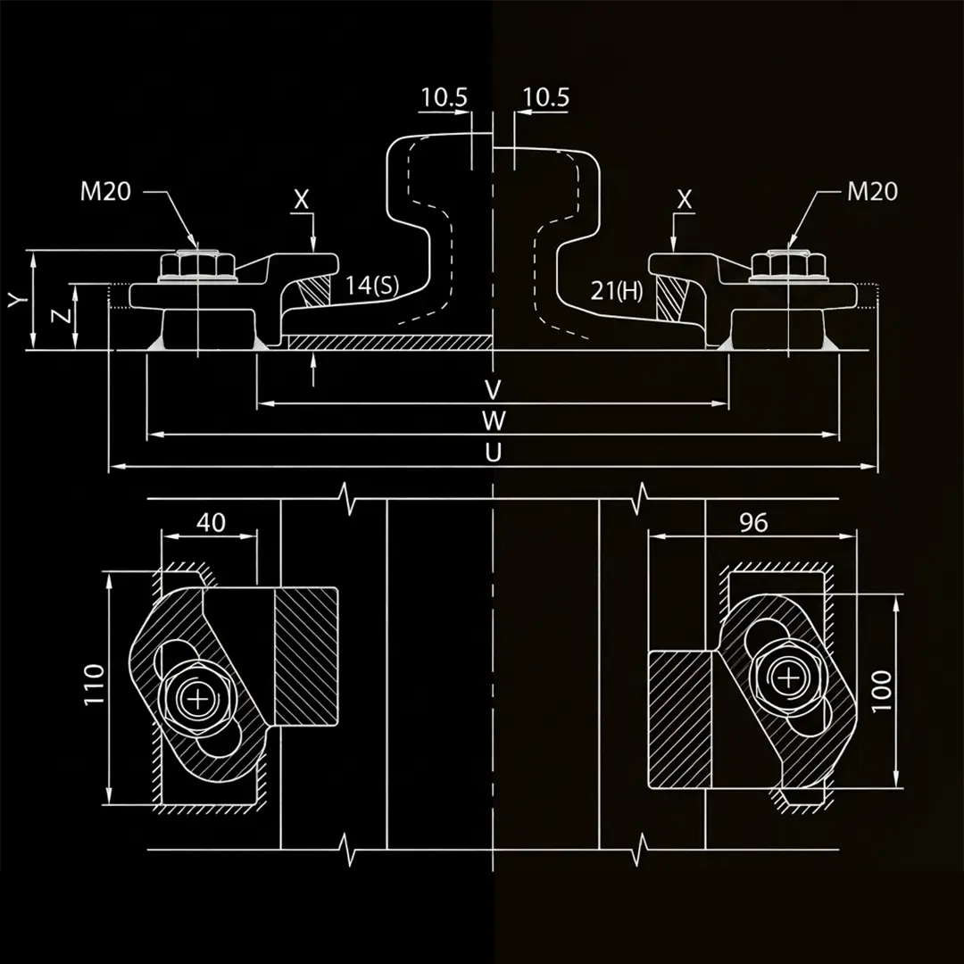
Applying these formulas to the three rail profiles gives the following results:
| Rail Profile | V (mm) | W (mm) | U (mm) | Inward Shift of Each New Base Compared with A100 |
|---|---|---|---|---|
| A100 | 222 | 320 | 362 | — |
| QU100 | 172 | 270 | 312 | 25 mm |
| QU80 | 152 | 250 | 292 | 35 mm |
These dimensions reveal three important points:
- The new clip bases must be positioned closer to the rail centerline. Compared with the original A100 layout, each base moves inward by 25 mm for QU100 and 35 mm for QU80. The existing A100 bases are therefore misaligned with the new rail profiles and cannot simply be used in their original positions.
- The upper clip’s adjustment range is for installation adjustment, not base relocation. The horizontal adjustment allows fine positioning and accommodates installation variations. It should not be relied on to compensate for a 25–35 mm change in the welded base positions. The bases must be placed correctly before welding.
- The new and existing base footprints will overlap if installed at the same longitudinal position. The maximum width of a W120 welded base is 40 mm. Since each new base shifts inward by 25 mm for QU100 or 35 mm for QU80, the projected footprints will overlap by approximately 15 mm and 5 mm, respectively. The adjustable upper section has a maximum width of 96 mm, which must also be considered when checking the overall assembly clearance.
This means the new bases cannot simply be welded at the required inward positions while leaving the original bases in place at the same longitudinal position. The layout must be changed to avoid physical interference. This is a key constraint when choosing a modification method.
Pre-Modification Assessment: Measure First, Then Choose a Solution
Before cutting, welding, or drilling, check the actual dimensions and layout of the existing soleplates. The following steps help determine which modification option is suitable.
- Mark the new base positions: Use the V dimensions calculated in the previous section and the W120 installation drawing to mark the theoretical positions of the new bases on the soleplate, using the new rail centerline as the reference. Also check the overall assembly dimensions against W and U.
- Measure the existing bases: Measure the actual position, outer dimensions, and weld footprint of each existing A100 base relative to the rail centerline. Do not rely solely on the original drawings, as actual welding deviations on stock soleplates may differ from the specified dimensions.
- Check for lateral interference: Compare the projected footprints of the existing and new bases at the same longitudinal position. As explained in the previous section, interference is expected with the W120 configuration.
- Check the available longitudinal space: Determine whether the new pair of bases can be shifted together along the rail direction to avoid the existing bases. The revised layout must still meet the required clip spacing and installation arrangement for the new project.
- Select the modification option:
- Sufficient longitudinal clearance available: Option 1 – Retain the existing bases and weld new bases in alternative positions.
- Insufficient longitudinal clearance: Option 2 – Remove the existing bases and weld new ones in the required positions.
- Avoiding hot work is preferred: Option 3 – Consider bolted rail clips, subject to product compatibility, load capacity, hole layout, and installation access requirements.
For batch modification, a marking template can be prepared using an approved reference layout. Check the first modified soleplate before applying the same layout to the remaining stock to maintain consistent positioning.
Option 1: Keep the Existing Bases and Weld New Bases at Offset Positions
When to use this option: The soleplate has sufficient length along the rail direction to accommodate the new bases and their complete welds outside the existing base footprints. The revised positions must also meet the new project’s rail clip spacing requirements.
The existing bases can remain in place without carrying any load from the new rail. However, they must not interfere with rail pad installation, welding operations, or clearance for the new rail clips.
Key Installation Considerations
1. Remove the Zinc Coating Locally
The zinc coating must be removed from the welding areas before welding. Zinc melts at approximately 420°C and boils at approximately 907°C. During welding, zinc vapor can enter the weld pool and cause defects such as porosity. Zinc fumes can also cause metal fume fever if inhaled.
There is no need to remove the coating from the entire soleplate. According to the American Galvanizers Association (AGA), zinc should generally be removed 25–100 mm beyond each side of the intended weld area, with the exact range determined by the WPS. Mechanical grinding with an angle grinder is a common method.
The prepared surface must be free of residual zinc and other contaminants. This is essential because the load capacity and stability of welded rail clips depend heavily on weld quality.
2. Weld According to the W120 Installation Requirements
The W120 welded base is made from weldable-grade steel. The main requirements are:
- 5 mm fillet weld throat thickness.
- Low-hydrogen electrodes, such as AWS E7018 or E7028.
- Weld around the base as specified in the W120 installation drawing. When no rail pad is used, omit the weld parallel to the rail on the rail side.
- Tighten the upper M20 bolt to 350 N·m.
On relatively thin soleplates, control heat input and use a balanced welding sequence to minimize distortion.
Contact Glory Track for detailed installation drawings and project-specific requirements.
3. Restore the Galvanized Coating After Welding
Welding damages the zinc coating around the weld and heat-affected area. Repair the exposed steel in accordance with ASTM A780/A780M. Common methods include zinc-rich paint, zinc-based solder, and zinc metallizing.
Zinc-rich paint is a common option for local repairs. The selected coating must meet the project’s corrosion protection requirements. Do not leave the welded areas exposed to corrosion.
Option 2: Remove the Existing Bases and Weld New Ones
When to use this option: The soleplate does not have enough longitudinal space to offset the new bases, or the existing bases interfere with the new layout. This option requires an additional removal process but provides a clear installation area and is a practical solution when base interference cannot be avoided.
Removal and Surface Preparation
- Remove the old bases using a controlled cutting method. Avoid cutting directly into the root of the existing welds. The bulk of the base should be removed first, leaving the remaining weld metal for separate removal. The method should be selected based on the soleplate thickness and site conditions. Air carbon arc gouging may be used for weld removal, but requires careful control of heat input and must be followed by grinding.
- Grind the remaining weld metal and cutting marks flush with the soleplate surface, ensuring a smooth transition without sharp edges or deep grooves. These defects can act as stress concentrators.
- Inspect the soleplate after grinding. Check for gouges, cracks, and excessive material loss, and verify that the remaining plate thickness is adequate.
- After cutting and grinding, inspect the soleplate and ensure that the new weld areas are free of coatings and contaminants. Once the new bases have been welded, repair all damaged galvanized areas in accordance with ASTM A780/A780M.
Option 3: Switch to Bolted Rail Clips (Glory Track 3120 / 3220)
If hot work is not permitted and the existing bases can remain without interfering with the new installation, a third option is to use bolted rail clips. With conventional bolted fixing, this requires drilling holes in the soleplate instead of welding new bases.
Glory Track 3120 and 3220 clips are compatible with A100, QU80, and QU100 rails. The main differences are the number of fixing bolts and the load capacity.
| Model | Number of Bolts | Maximum Lateral Load | Minimum Assembly Width | QU100 Width | QU80 Width |
|---|---|---|---|---|---|
| 3120 | 1 | 75 kN (approx. 7.6 tf) | Rail base width + 147 mm | 297 mm | 277 mm |
| 3220 | 2 | 150 kN (approx. 15.2 tf) | Rail base width + 147 mm | 297 mm | 277 mm |
For reference, the minimum assembly width for an A100 rail under this formula is 347 mm. Therefore, if the existing soleplates have an effective width of at least 347 mm, they should have sufficient width for the 3120 or 3220 clips with the narrower QU rails.
Three Things to Check Before Installation
1. Access to the Underside of the Soleplate
The fixing bolts must be inserted and tightened from the side specified in the installation drawing. If the soleplates have not yet been installed and their undersides are accessible, installation should be straightforward. However, if they are already sitting on grout or concrete with no access underneath, the bolted option may not be practical. In that case, consider a welded solution instead.
2. Load Capacity
The 3120 has a maximum lateral load rating of 75 kN, while the 3220 is rated at 150 kN. Select the model based on the project’s design lateral load, taking crane wheel loads and operating conditions into account. Do not use a model if the required load exceeds its rated capacity.
3. Hole Layout
Follow the installation drawing for hole diameter and edge distances. For thin soleplates or holes located close to the plate edges, also check the effect of drilling on the plate’s load capacity.
Two More Details Not to Overlook
- The zinc coating still needs attention. Switching to bolted clips avoids grinding off the zinc coating for welding. However, drilling and deburring damage the galvanized layer around the holes. These exposed areas must still be repaired with zinc-rich paint or another approved coating repair method. The repair area is smaller than with welding, making the process simpler, but it should not be skipped.
- The existing bases must still be checked for interference. The minimum assembly width for 3120/3220 is the rail base width plus 147 mm, compared with the rail base width plus 120 mm for the W120 welded clip. Check the actual positions and dimensions of the old bases against the new bolted clip layout. Remove them if they interfere; otherwise, they can remain in place. Note that removing welded bases may still involve cutting or grinding, even when the new clips are bolted.
Comparison of the Three Modification Options
| Comparison Item | Option 1: Keep Existing Bases and Add New Welded Bases | Option 2: Remove Existing Bases and Weld New Ones | Option 3: Switch to Bolted Rail Clips |
|---|---|---|---|
| Existing Base Treatment | Leave in place | Cut off and grind flush | Leave in place or remove if necessary |
| Zinc Coating Treatment | Locally remove zinc around new weld areas; repair after welding | Remove zinc around new weld areas; repair all coating damaged by cutting, grinding, and welding | No welding-related zinc removal; repair drilled holes and damaged coating |
| Hot Work Required | Yes | Yes | No for clip installation; removal of old bases may require hot work |
| Main Limitation | Sufficient longitudinal space for the new bases and welds | Avoid damaging or thinning the soleplate during base removal | Adequate installation access and sufficient load capacity |
| Load Capacity Basis | Weld design and quality; soleplate capacity must also be verified | Weld design and quality; soleplate capacity must also be verified | Maximum lateral load: 75 kN (3120) / 150 kN (3220) |
| Impact on Soleplate | Welding heat and local coating repair | Additional cutting and grinding, followed by welding and coating repair | Drilled holes and local coating repair |
| Relative Workload | Low | Moderate | Lowest, provided the installation conditions are suitable |
Frequently Asked Questions
Q1: Will Removing the Old Bases Affect the Strength of the Soleplate?
The impact depends on how the bases are removed. Cutting and grinding may cause local material loss or surface damage. After removal, grind the remaining weld metal smooth without unnecessarily removing the parent metal. Check for gouges, cracks, and reduced plate thickness. If significant damage is found, further inspection is required before reuse.
Q2: Will Areas with the Zinc Coating Removed Rust First?
Exposed steel can corrode if left unprotected. After welding, repair the damaged galvanized coating in accordance with ASTM A780/A780M, using an approved method such as zinc-rich paint. The repair coating must meet the project’s thickness and corrosion protection requirements. In outdoor or highly corrosive environments, the repaired areas should be included in the project’s corrosion protection plan and inspected periodically.
Q3: Can Welding Cause the Soleplate to Distort?
Yes. The risk is generally higher with thinner soleplates. Use a balanced welding sequence, control heat input, and apply suitable back-step or skip welding techniques where appropriate. Check the soleplate’s flatness after welding. Any required straightening should follow an approved procedure, as flatness affects the contact between the rail, rail pad, and soleplate.
Q4: How Should We Choose Between the 3120 and 3220?
The choice depends on the required lateral load. The 3120 has one fixing bolt and a maximum lateral load of 75 kN, while the 3220 has two fixing bolts and a maximum lateral load of 150 kN. Select the model based on the new crane’s design lateral load, taking wheel loads and operating conditions into account. Contact Glory Track with the project parameters if you need help checking the selection.
Q5: Can the Existing A100 Rail Pad Still Be Used?
Not necessarily. The existing rail pad should be checked for width, thickness, material, and compatibility with the new rail support arrangement. A100 has a 200 mm rail base, compared with 150 mm for QU100 and 130 mm for QU80. If the existing pad does not provide the required support or interferes with the new installation, it should be replaced with a suitable pad for the new rail profile. Also check the condition and flatness of the soleplate during modification.
Q6: Does the Soleplate Thickness Need to Be Rechecked for the New Project?
Yes. The existing soleplates were originally designed for the previous project’s operating conditions, which may differ from those of the new crane. Check the plate thickness and material against the new design loads, support conditions, rail clip spacing, anchorage, and grout requirements. This is another reason to review the new project’s technical parameters before reusing the existing soleplates.
Send Us Your Soleplate Details
Every batch of existing soleplates comes with different conditions. The plate length determines whether the new bases can be repositioned along the rail. Plate thickness affects the risk of welding distortion and drilling. The new project’s load requirements determine whether bolted rail clips are suitable. These factors cannot be fully evaluated from this article alone.
If you have existing stock soleplates that need to be adapted for a new project, send the drawings or site photos to the Glory Track technical team, along with the new rail profile and crane specifications.
We can help assess whether the existing bases should be retained or removed, recommend a suitable option from the W120, 3120, and 3220 rail clip models, and provide the corresponding installation drawings and welding recommendations.
For detailed W120 specifications and installation instructions, see our W120 rail clip installation guide. For project-specific installation details, contact the Glory Track team directly.