
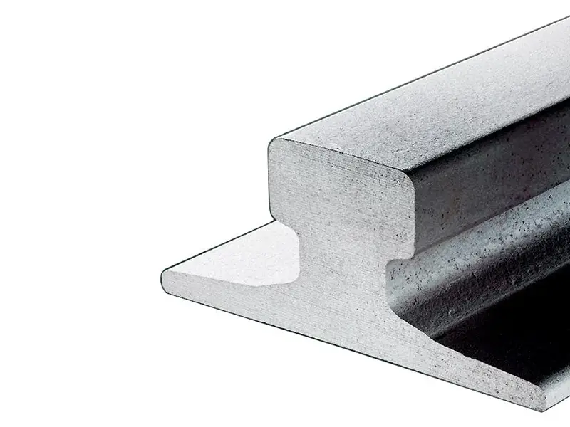
Crane rail joints on DIN 536 A-series tracks are normally made by welding. Fishplates are not commonly used with these profiles, although custom fishplate connections can be considered for projects with specific requirements. The right connection method depends on the rail profile, material, operating loads, and installation conditions.
Rail length and end preparation also need to be considered before installation. From standard welded joints to custom fishplate designs and angled cutting, each requirement should be checked against the project drawings.
Why Do DIN 536 A-Series Rails Need Profile-Specific Joint Designs?
DIN 536 A-series crane rails have a distinctive cross-section with a wide base, relatively thick web, and a profile designed for crane wheel loading. The series includes seven main profiles, from A45 to A150, with different dimensions and sectional properties.
DIN 536-1 specifies the dimensions, sectional properties, and steel grades for Type A crane rails. It does not prescribe a single joining method. The joint arrangement must therefore be selected according to the actual rail profile and project requirements.
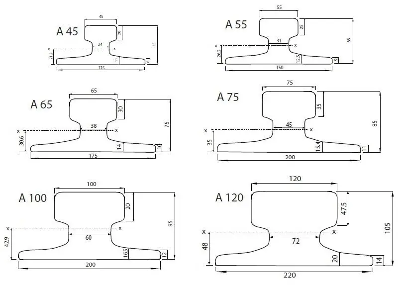
DIN 536 A-Series Rail Dimensions
| Profile | Head C (mm) | Foot F (mm) | Web t (mm) | Height A (mm) | Mass (kg/m) |
|---|---|---|---|---|---|
| A45 | 45 | 125 | 24 | 55 | 22.1 |
| A55 | 55 | 150 | 31 | 65 | 31.8 |
| A65 | 65 | 175 | 38 | 75 | 43.1 |
| A75 | 75 | 200 | 45 | 85 | 56.2 |
| A100 | 100 | 200 | 60 | 95 | 74.3 |
| A120 | 120 | 220 | 72 | 105 | 100 |
| A150 | 150 | 220 | 80 | 150 | 150.3 |
A conventional fishplate joint uses two joint bars fitted against the rail web on opposite sides of the rail ends. Bolts pass through the bars and the rail web to secure the connection.
However, a fishplate designed for another rail profile should not automatically be considered compatible with a DIN 536 A-series rail. The available web area, contact geometry, bolt positions, and installation clearance all need to be checked.
This is why welded joints are the usual connection arrangement for A-series rails, while bolted fishplate connections require a profile-specific review.
How Are DIN 536 A-Series Crane Rails Joined by Welding?
Welding is the usual method for connecting adjacent DIN 536 A-series rail sections into a continuous track. It avoids the need for a conventional bolted joint bar and can provide a continuous running surface when the joint is properly designed and executed.
Several welding methods are used in crane rail systems. The appropriate process depends on the rail steel grade, cross-section, site conditions, available equipment, and approved welding procedure.
Common Welding Methods for Crane Rails
Aluminothermic, or thermite, welding uses a chemical reaction to produce molten steel that fills the gap between prepared rail ends. It is commonly used for field rail joining, particularly where the equipment needed for flash-butt welding is not available.
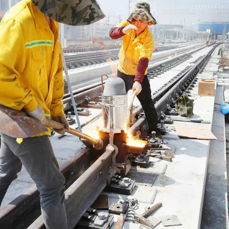
The rail profile, steel grade, joint gap, and welding portion must be compatible with the selected procedure.
Flash-Butt Welding
Flash-butt welding joins rail ends through electrical resistance heating and applied pressure. It generally requires specialized equipment and controlled working conditions, making it more suitable for production or projects where the rails can be brought to an appropriate welding facility.
Enclosed Arc Welding
Enclosed arc welding is another method identified in crane rail engineering guidance. Its suitability depends on the rail section, material, joint configuration, and qualified welding procedure.
These methods are not interchangeable, and none should be selected solely on the basis of the A-series rail designation.
What Needs to Be Controlled at a Welded Joint?
A reliable welded joint depends on more than the welding process itself. Several details need to be coordinated:
- Rail-end preparation: The ends must be clean and prepared according to the selected welding procedure.
- Joint alignment: Adjacent rail sections need to be aligned in both the vertical and horizontal planes.
- Joint gap: The required gap must follow the approved welding procedure rather than a general rule applied to every profile.
- Material compatibility: The welding procedure and consumables must be suitable for the specified rail steel.
- Post-weld grinding: The finished running surface must be properly ground where required.
- Inspection: The completed joint should be checked for alignment and weld defects using the inspection methods specified for the project.
Standard welded joints be square to the rail’s longitudinal axis, that welds be ground flush at the rail head and foot, and that suitable inspection methods, including ultrasonic testing where appropriate, be used. The specific welding procedure, inspection requirements, and acceptance criteria should be agreed before installation.
Can DIN 536 A-Series Crane Rails Be Joined with Fishplates?
Fishplates are not commonly used with DIN 536 A-series crane rails, but custom options can be considered for special project requirements.
A conventional fishplate is designed around a particular rail section. Its dimensions and bolt arrangement must match the rail web and provide sufficient contact and clearance. A standard joint bar intended for another rail profile should therefore not be assumed to fit A-series rails.
What Needs to Be Checked for a Custom Fishplate?
Before a custom fishplate connection is considered, the following details should be reviewed:
| Design item | What needs to be checked |
|---|---|
| Rail web geometry | Available contact area and web dimensions |
| Fishplate dimensions | Plate thickness, length, and contact surfaces |
| Bolt arrangement | Bolt diameter, hole positions, and spacing |
| Edge distances | Adequate material around the bolt holes |
| Joint alignment | Control of vertical and lateral displacement |
| Operating conditions | Wheel loads and service requirements |
| Installation access | Space for bolting, inspection, and maintenance |
Drilling and bolting arrangements should be approved as part of the joint design. Unverified drilling or the use of an off-the-shelf fishplate can compromise the intended connection.
How Does Glory Track Handle Special Fishplate Requirements?
For projects that require bolted connections, customers can submit the rail profile, technical drawings, and joint requirements to Glory Track’s technical team.
The proposed connection can then be reviewed against the actual rail cross-section and project conditions. If a suitable custom design can be developed, the fishplate dimensions and bolting arrangement can be confirmed before production.
Custom fishplate solutions are therefore a project-specific option, not a standard accessory that can be assumed to fit every A-series profile.
For more information about fishplate types, materials, and selection considerations, see our Fish Plates Guide.
How Should DIN 536 Rail Ends Be Prepared?
Rail-end preparation depends on the selected joint design. Straight cutting is commonly used for standard welded joints, while angled cutting and local rail-head beveling may be specified for particular project requirements.
Straight Cutting for Welded Joints
For conventional welded butt joints, rail ends are generally prepared with square cuts perpendicular to the rail’s longitudinal axis.
Accurate end preparation helps maintain the required alignment and joint gap during welding. The final end condition must follow the selected welding procedure.
Angled Rail-End Cutting at 45° or 60°
Some projects require rail ends to be cut at a specified angle, such as 45° or 60°. These cuts can be processed according to customer drawings and the requirements of the intended joint arrangement.
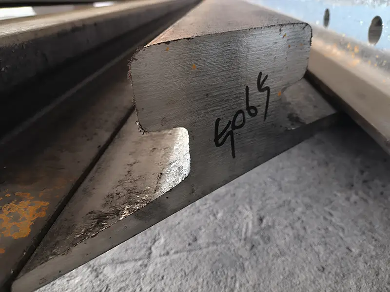
An angled cut should not automatically be treated as a standard welded-joint preparation. The drawing needs to show whether the requirement concerns the full rail-end face, a local portion of the profile, or another specific joint geometry.
Rail-Head Beveling
Rail-head beveling is different from cutting the entire rail end at an angle. It modifies a specified area of the rail head to create a controlled transition at the running surface.
When designed for the wheel profile and joint arrangement, this treatment may help reduce the abrupt impact as a wheel passes over a joint, improving running smoothness and helping to limit vibration and noise.
The bevel dimensions and machining position should be specified on the project drawing.
What Rail Lengths and Cutting Tolerances Are Available?
DIN 536 A-series crane rails are normally stocked in 12-meter lengths per piece by Glory Track. Custom cutting is available to match project-specific rail lengths and installation layouts.
| Processing Item | Glory Track Supply Information |
|---|---|
| Standard stock length | 12 m per piece |
| Custom length | Available upon request |
| Default cutting-length tolerance | ±5 mm |
| Special tolerance | Subject to prior confirmation |
| Cutting options | Straight and angled cutting |
| Common requested angles | 45° and 60°, subject to drawing review |
| Additional processing | Rail-head beveling and other specified end machining |
The default ±5 mm tolerance applies to cutting length when no special requirement has been provided. It is not an installation tolerance or a permitted welding-joint gap.
For projects requiring tighter dimensional control, customers should provide the required finished length and tolerance before production. Glory Track can review the drawings and confirm the cutting arrangement before processing.
Need DIN 536 A-Series Rails with Special Joint Preparation?
Whether your project requires standard 12-meter rails, custom cut lengths, welded-joint preparation, or a specially designed fishplate connection, Glory Track can review the requirements based on the rail profile and project drawings.
Send us your rail model, required lengths, joint details, and technical drawings to discuss a suitable supply and machining plan.