
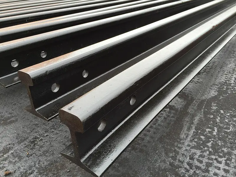
Why Is Custom Rail Drilling Needed?
Depending on the rail type and joint design, crane rails may be supplied without holes or with fishplate holes pre-drilled at the ends. Other holes, whether for mounting, fastening, or project-specific connections, are generally machined to meet the customer’s drawings or agreed requirements.
When ordering crane rails, the key is not simply whether drilling is required. Three questions need to be clarified:
- What is each hole intended for?
- Where should each hole be located, and what diameter, quantity, and spacing are required?
- Which drawing, technical specification, or applicable standard defines the hole pattern, dimensions, and machining tolerances?
Without these details, the rails may arrive on site but fail to fit the connecting components or supporting structure as intended.
Three Types of Crane Rail Holes by Function
Based on their intended use, custom crane rail holes can be grouped into three categories. Each type has different machining locations, connection requirements, and design references.
| Hole Type | Typical Application | Location and Orientation | Loads to Consider | Design Reference |
|---|---|---|---|---|
| 1. Fishplate Holes | Bolted connections between two rail sections using fishplates (rail joint bars) | Through the rail web near both ends, with holes arranged along the rail length. The number and spacing depend on the fishplate design. | Joint bending and shear forces, plus dynamic effects as crane wheels pass over the joint | Matching fishplate drawings, rail profile, and joint design |
| 2. Rail Fastening Holes | Directly bolting the rail to its supporting structure, including hook-bolt fastening through the web and direct bolting through the rail foot | Hook bolt holes: drilled through the rail web. Rail foot holes: drilled at specified locations in the rail foot. Hole positions, orientation, and spacing depend on the connection design. | Clamping forces, lateral forces, uplift, and longitudinal forces from the fastening arrangement, as well as local stresses around the holes | Rail profile and dimensions, supporting structure drawings, bolted connection design, and project requirements |
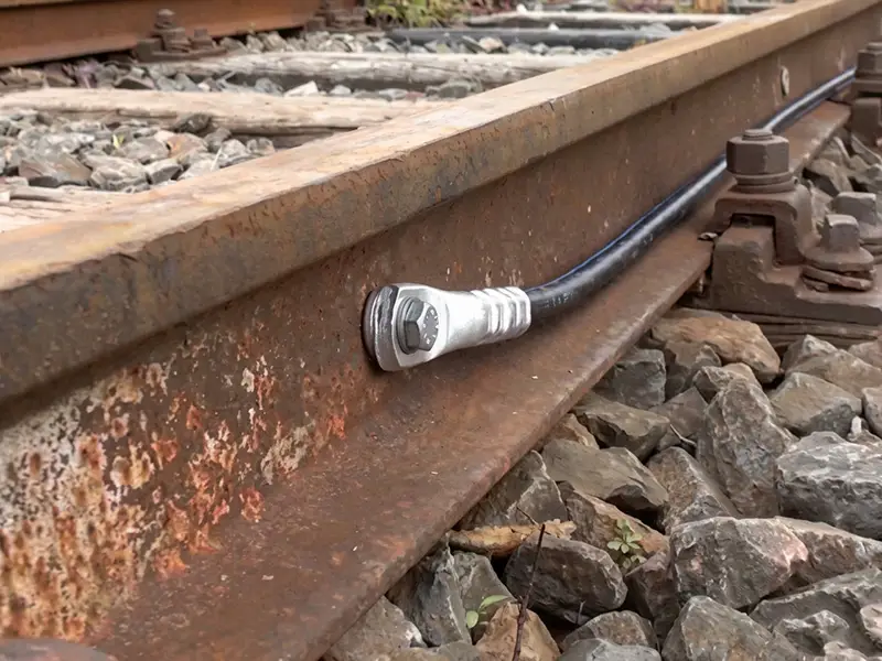
| 3. Special-Purpose Holes | Sensor mounting, electrical bonding, measurement references, and interfaces for project-specific equipment. Lifting or handling holes should only be included where specified in an approved lifting design. | Machined at the locations and orientations specified in the approved project drawings | Determined by the intended application, including equipment weight, vibration, or temporary lifting loads | Approved project drawings, equipment requirements, and necessary engineering calculations |
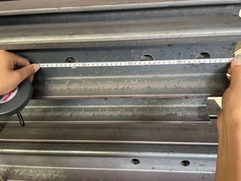
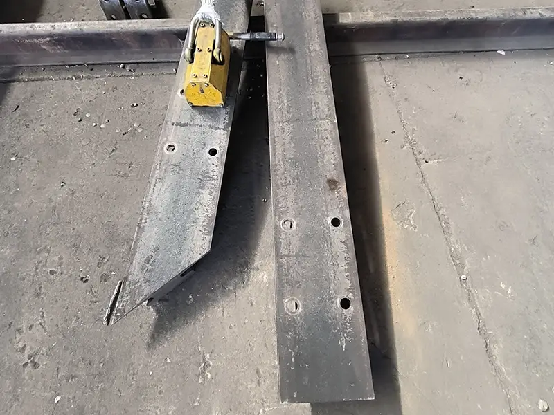
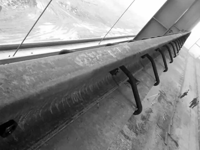
Fishplate Holes
The Hole Pattern Follows the Joint Design
For QU70–QU120 crane rails, YB/T 5055-2025 specifies rail ordering requirements, cross-sectional dimensions, profiles, mass, and technical requirements. However, it does not define a universal drilling pattern for fishplate joints.
The QU rail designation alone is therefore insufficient to determine the rail-end drilling. Hole quantity, diameter, spacing, and end distance must be confirmed against the matching fishplate and approved joint drawing.
For example, ordering “QU100 with 6 holes” does not fully define the machining requirements. The drawing must show the hole positions and clarify whether the specified quantity refers to one fishplate, one rail end, or the complete joint assembly.
Fishplates may also be designed with four-hole or six-hole arrangements. The hole count alone does not determine joint capacity. Fishplate dimensions, bolt arrangement, rail profile, wheel loads, and operating conditions must be considered together when selecting the joint configuration.
QU-Series Fishplate Dimensions
The following table provides reference dimensions for QU-series fishplates supplied by Glory Track. These dimensions represent our available product configurations.
| Rail Type | Length × Width × Thickness (mm) | Hole Dia. (mm) | Hole Spacing (mm) |
|---|---|---|---|
| QU70 | 760 × 70 × 20 | 24 | 90 / 105 |
| QU80 | 820 × 75 × 20 | 24 | 100 / 120 |
| QU100 | 950 × 80 × 22 | 26 | 105 / 125 |
| QU120 | 1,050 × 85 × 26 | 26 | 110 / 130 |
Actual hole positions, end distances, and bolt compatibility should be confirmed against the corresponding fishplate drawing. Custom fishplate dimensions and hole patterns can also be supplied according to project requirements.
American CR-Series Rails
American CR-series crane rails use different rail-end drilling patterns. Their hole dimensions should not be taken from QU-series fishplate specifications.
For example:
| Rail Type | Hole Diameter |
|---|---|
| CR104 | 26.99 mm |
| CR105 | 23.81 mm |
| CR135 | 30.16 mm |
| CR171 | 30.16 mm |
| CR175 | 30.16 mm |
Hole spacing, elevation, and the number of holes at each rail end must also be checked against the corresponding drilling drawing.
DIN 536 A-Series Crane Rails
DIN 536 A-series crane rails are commonly joined by welding. When a bolted fishplate connection is specified, the plate design and hole arrangement must be confirmed for the selected A-series rail profile. See our guide to DIN 536 A-Series Crane Rail Joints.
Mounting and Fastening Holes
Unlike fishplate holes, mounting and fastening holes are determined by the rail fastening arrangement and supporting structure. This section covers holes drilled directly into the rail web or foot. Bolt holes in the runway beam or baseplate for conventional rail clips are not classified as rail drilling.
Rail-to-Support Fastening Holes
Crane rails are commonly secured to runway beams or baseplates using rail clips or clamps. When the available beam width or site restrictions prevent the use of conventional fastening systems, alternative connection details may be considered.
One option is hook bolt fastening. Holes are drilled through the rail web so that hook bolts can engage the supporting beam flange or channel. The threaded shank passes laterally through the rail web, while the hooked end wraps around the supporting structure. Tightening the nut pulls the rail toward the support without requiring bolt holes in the beam flange.
Another project-specific option is direct rail foot bolting, where holes are drilled through the rail foot and bolts secure the rail directly to the supporting structure.This provides a direct bolted connection. The rail foot, bolt arrangement, supporting structure, and requirements for longitudinal rail movement must all be checked before machining.
Hook Bolt Holes: Diameter and Layout
Hook bolt holes must match the rail profile, actual bolt dimensions, and supporting beam arrangement. The following factors should be confirmed before drilling:
Hole Diameter: Determine the hole diameter from the actual bolt shank, required clearance, and manufacturer’s specifications. A fixed allowance of 2 mm above the nominal bolt diameter should not be applied to every hook bolt.
Hole Elevation: Follow the approved rail and hook bolt drawing. Keep the holes clear of the curved transitions between the rail head, web, and foot, while maintaining sufficient material around each hole.
Hole Spacing: Hook bolts are commonly arranged in opposing pairs or project-specific patterns. Their spacing depends on the rail section, beam geometry, and fastening design. Published reference arrangements should not be treated as universal drilling dimensions.
Edge and End Distances: Check the remaining material around each hole, including distances to the rail ends and profile transitions. Local bearing, net-section strength, tear-out, and fatigue also need to be considered.
Accessory Mounting Holes
Some projects require holes directly in the rail for mounting brackets, sensors, electrical bonding terminals, or other purpose-designed accessories. The hole quantity, orientation, and location are determined by the corresponding installation drawings.
When several hole types are required, combine the fishplate, fastening, and accessory hole locations in one coordinated rail drilling drawing. This helps prevent interference between different hole patterns and avoids repeated machining changes.
What Information Is Required When Ordering Drilled Rails?
Custom rail drilling requires more than specifying the hole diameter and quantity. The hole locations, reference datums, mating components, and machining tolerances must also be clear before production.
| No. | Required Information | Purpose |
|---|---|---|
| 1 | Rail profile and applicable product standard (e.g., QU100 to YB/T 5055-2025, A100 to DIN 536, or an 85-lb ASCE rail); steel grade, if specified. | Identify the rail section and material |
| 2 | Length per rail, total quantity, and number of drilled ends | Determine the machining scope and hole distribution |
| 3 | Hole type and intended application (Fishplate, Rail Fastening, or Special-Purpose) | Establish the connection type and machining requirements |
| 4 | Hole diameter, quantity, spacing, and end distance | Define the hole pattern |
| 5 | Positioning datums and hole orientation | Locate holes relative to the rail end, web centerline, or other specified datum |
| 6 | Matching component details (fishplate, bolts, hook bolts, or accessory drawings) | Ensure compatibility with the mating components |
| 7 | Machining tolerances and surface protection requirements | Control hole dimensions, positions, and corrosion protection |
| 8 | Reference drawings, CAD files, or physical samples | Clarify the required geometry and machining orientation |
Common Rail Supply Lengths and End-Drilling Configurations
The following table summarizes common supply lengths and end-drilling configurations offered for reference.
| Rail Profile | Common Supply Length | Typical End-Drilling Configuration | Notes |
|---|---|---|---|
| A45–A150 | 12 m | Usually supplied undrilled | Welded joints are common. Fishplate holes require a separate design |
| QU70–QU120 | 12 m, cut to order | Usually supplied undrilled | Specify fishplate drilling before production |
| Light Rails, 8–30 kg/m | 6 m; 8 m and 10 m subject to availability | 2 holes at each end (4 per rail) | Other hole patterns are available by request |
| Heavy Rails, 38–50 kg/m | 12.5 m; 12 m cut lengths available | 3 holes at each end (6 per rail) | Other hole patterns are available by request |
Frequently Asked Questions
Q1: Can a crane rail be drilled at one end only?
Yes. Short rails, expansion joints, and special connection designs may require drilling at only one end. The drilled end and free end should be clearly identified on the drawings and marked on the rails and packaging to prevent installation errors.
Q2: Can holes be drilled in crane rails after installation?
Yes, subject to an approved site machining procedure. A magnetic drill with a positioning template can be used where the mounting surface allows secure attachment. The work area must be secured, the rail taken out of service, and the finished holes deburred and protected against corrosion.
Q3: Can fishplate holes and fastening holes be drilled in the same rail?
Yes. However, all hole patterns should be coordinated on one drilling drawing. Hole spacing, edge distances, the remaining web section, and bolt installation clearance must be checked to prevent interference.
Q4: Can the hole diameter be exactly the same as the bolt diameter?
Standard clearance holes are generally slightly larger than the bolt shank to allow assembly. Closer fits may be specified for fitted bolts or reamed connections. The final hole diameter must follow the fastener dimensions, connection design, and applicable tolerances.
Get Your Custom Rail Drilling Requirements Checked
Custom rail drilling is not just about making holes in the right size. Hole locations, mating components, and machining tolerances all need to be confirmed before production.
Send Glory Track your rail profile, required hole pattern, and matching component drawings. Our team can review the drilling requirements and help confirm a suitable processing solution.