
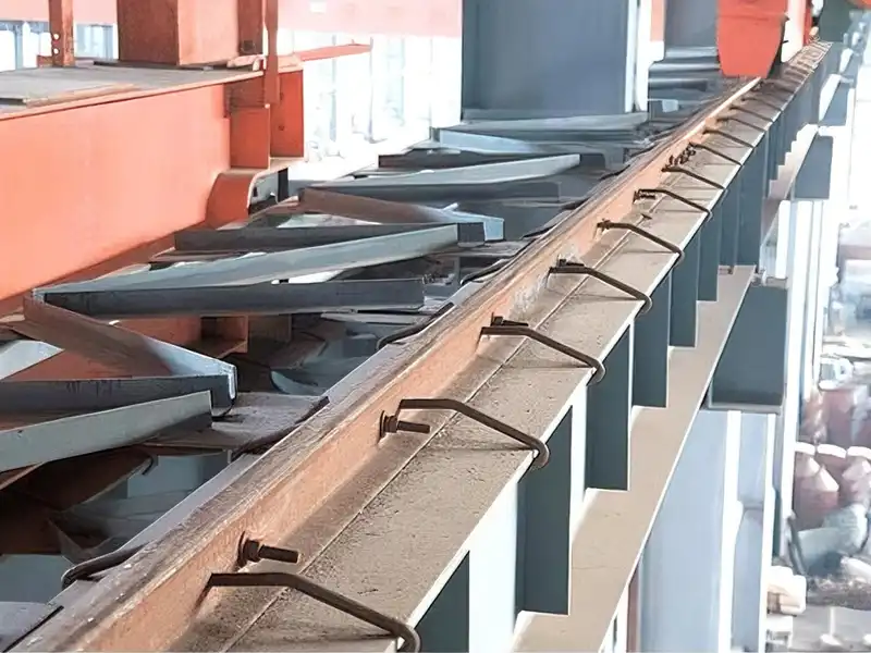
For overhead and gantry crane runway installations, the width of the steel beam’s top flange directly affects the choice of crane rail fasteners.
Standard welded rail clips typically use mounting bases positioned on both sides of the rail. The rail is secured by bolting the top covers to these bases. When the beam flange is too narrow to provide sufficient mounting space for the clip bases, standard fastening arrangements may not be feasible.
This situation is relatively common in existing facility upgrades and projects with limited structural clearance. Replacing the steel beam may require substantial structural modifications, while simply using smaller clips, reducing the number of clips, or fastening the rail on only one side does not necessarily provide reliable restraint.
For narrow-beam applications, two crane rail fastening methods are worth considering: the SWJK compact welded rail clamp and crane rail hook bolts. These methods use different connection designs and have different application requirements. The right choice depends on first confirming the beam’s effective support width, then evaluating the available mounting space and crane operating conditions.
1. How to Determine Whether the Beam Width Is Sufficient for Rail Fastening
Start by measuring two dimensions:
- B: Usable steel beam flange width (Effective Flange Width).
- F: Rail foot width.
When the rail is centered on the beam and B is greater than F, the available clearance on each side is:
For example, an A100 crane rail has a foot width of 200 mm. If the usable beam flange width is 250 mm, the rail has 25 mm of clearance on each side.
However, this does not necessarily mean standard rail clips can be installed. The available space must also accommodate the clip bases, bolt positions, and required welding clearance.
Based on these dimensions, three installation conditions can be identified:
Case 1: The Beam Flange Is Narrower Than the Rail Foot (B < F)
Part of the rail foot extends beyond the beam flange, creating an unsupported overhang. In this case, the issue goes beyond fastener installation. The effective support area under the rail foot and the resulting local stresses must also be checked. Simply switching to different rail clips or crane rail hook bolts cannot resolve inadequate rail support.
Case 2: The Beam Flange Is Just Wide Enough to Accommodate the Rail Foot (B ≈ F)
The rail foot fits within the beam flange, but there is virtually no additional space on either side for mounting clip bases. Neither standard nor compact welded rail clips, can be accommodated in this condition because both require additional flange width for their mounting bases.
Hook bolts may be considered as an alternative, provided the beam flange edge can be securely engaged by the hooks and the crane operating conditions are suitable.
Case 3: The Beam Flange Is Slightly Wider Than the Rail Foot but Still Too Narrow for Standard Rail Clips (B > F)
The rail has adequate support, but the remaining clearance on both sides is insufficient for standard clip bases. Compare the minimum mounting widths of standard and compact rail clips against the actual beam dimensions. If neither type can be accommodated, crane rail hook bolts may be considered as an alternative, provided the beam flange and crane operating conditions are suitable.
2. Solution 1: Use SWJK Compact Welded Rail Clamps
The SWJK compact welded rail clamp is designed for applications where the installation dimensions of standard WJK rail clamps are restricted.
Compared with the standard WJK, the SWJK compact welded rail clamp requires less beam flange width for installation. For example, when used with 38kg rail, the minimum required beam flange width is 298 mm for SWJK, compared with 328 mm for standard WJK. This reduces the required flange width by 30 mm, making SWJK a suitable option for applications where the available flange width is insufficient for standard WJK clamps.
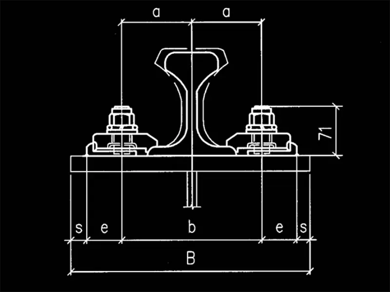
SWJK Components and Installation
The SWJK rail clamp consists of the following main components:
- Base Plate: Welded to the top flange of the steel beam to provide the mounting foundation for the fastening assembly.
- Top Cover: Contoured to match the rail foot profile and hold the rail in position.
- Adjustment Plate: Used to adjust the rail’s lateral position and gauge.
- T-Bolt: Connects the top cover to the base plate and provides the clamping force.
- Nut and Washers: Used to secure the assembly during final tightening.
The installation process involves the following steps:
Step 1: Measure and Position the Base Plates
Determine the rail centerline and the positions of the base plates on both sides of the rail according to the rail section and the installation dimensions of the selected SWJK model.
Before installation, verify that the actual beam flange width meets the minimum width requirement for the corresponding SWJK model.
Step 2: Weld the Base Plates
Position the SWJK base plates on both sides of the rail according to the installation drawing, then weld them to the steel beam using the specified welding procedure.
Depending on the design, the base plates may be welded along two sides or three sides. Weld size, length, and electrode selection must be matched to the base plate material, beam material, and crane duty requirements. Do not change the specified welding details without engineering approval.
Step 3: Install the Rail and Adjustment Components
Place the rail in its designated position, ensuring that the rail foot makes proper contact with the supporting surface.
Then install the T-bolts, adjustment plates, and top covers in the specified positions. Make sure the top covers are correctly seated against the corresponding contact areas on the rail foot.
Step 4: Adjust the Rail Gauge and Tighten the Assembly
Use the adjustment plates to fine-tune the rail’s lateral position. Once the rail centerline and gauge meet the project requirements, tighten the nuts to the specified torque for the selected model.
The SWJK T-bolt features a spherical joint at its lower end, allowing a certain degree of angular movement under lateral loading. The top cover restrains lateral rail movement while allowing limited longitudinal movement within the design range.
SWJK Installation and Fixing Requirements
| Item | Installation Requirements |
|---|---|
| Bolt Grade | 8.8 |
| Base Plate Connection | The base plates of the fixing units are welded to the crane girder. |
| Welding Electrodes | Select electrodes compatible with the materials being joined. For Q235 and Q345 steel, use E4315 and E5015 electrodes, respectively. |
| Fixing Unit Spacing | Determined by the crane’s rated lifting capacity (Q): 600 mm for Q < 275 t; 500 mm for Q > 275 t. |
Minimum Beam Flange Width Required for Different SWJK Models
The minimum beam flange width required for SWJK installation varies depending on the rail section. Therefore, a single flange width cannot be used as a universal requirement for all models.
The following table lists the reference minimum beam flange widths for common SWJK models:
| Clamp Model | Compatible Rail | Minimum Beam Flange Width, B (mm) |
|---|---|---|
| SWJK-TG38 | 38kg | 308 (298) |
| SWJK-TG43 | 43kg | 308 (298) |
| SWJK-TG50 | 50kg | 326 (316) |
| SWJK-TG60 | 60kg | 344 (334) |
| SWJK-QU70 | QU70 | 304 (294) |
| SWJK-QU80 | QU80 | 324 (314) |
| SWJK-QU100 | QU100 | 344 (334) |
| SWJK-QU120 | QU120 | 364 (354) |
Note: Values outside parentheses correspond to the s = 10 mm configuration, while values in parentheses correspond to the s = 5 mm configuration. The appropriate dimension should be selected according to the base plate welding arrangement and the corresponding installation drawing.
For example, when using the SWJK-QU100, the reference minimum beam flange width is 344 mm for the s = 10 mm configuration. If the available beam flange width is insufficient, the clamp cannot be installed as specified. The dimensions must be rechecked against the actual welding arrangement and installation drawing.
When Should You Choose SWJK?
The SWJK is a suitable option when the available beam flange width is insufficient for standard WJK clamps but still meets the minimum width requirement of the corresponding SWJK model.
It is particularly suitable for applications requiring a more compact clamp footprint and lower installation height, provided that welding can be carried out on the steel beam.
Before selecting an SWJK model, confirm that the available beam flange width meets the minimum requirement for the selected rail section and that the base plates can be installed according to the specified welding arrangement. The fixing unit spacing must also follow the requirements based on the crane’s rated lifting capacity. In addition to dimensional compatibility, the suitability of the complete rail fastening arrangement must be verified against the project’s wheel loads, lateral forces, and operating conditions.
3. Solution 2: Use Hook Bolts
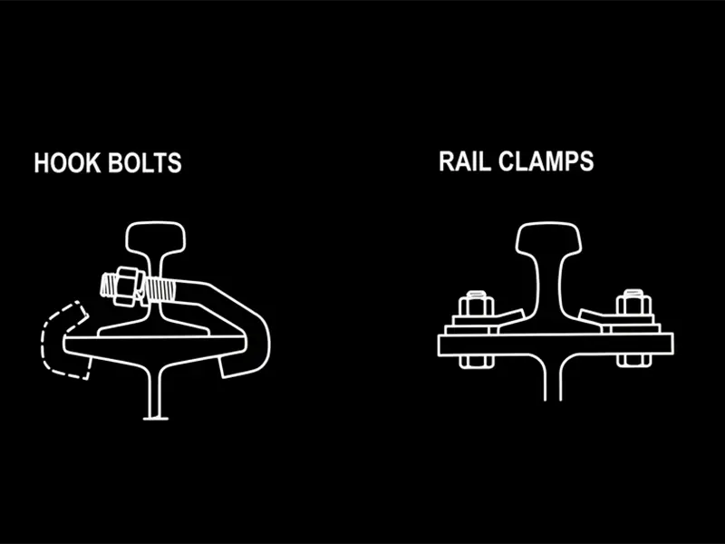
If the steel beam flange is too narrow to accommodate even the SWJK base plates, Hook Bolts can be considered as an alternative fastening method. This method uses a completely different connection design from welded rail clamps.
Hook Bolt Design and Fixing Principle
A typical hook bolt assembly consists of:
- Hook Bolt: A specially shaped bolt with a hooked end.
- Nut: Used to tighten the bolt and apply clamping force.
- Washers and Locking Components: Used for fastening and to help prevent loosening.
The bolt shank passes through a pre-drilled hole in the rail web, while the hooked end engages the underside of the outer edge of the steel beam flange. When the nut is tightened, the bolt applies a downward clamping force, pressing the rail foot firmly against the beam’s supporting surface.
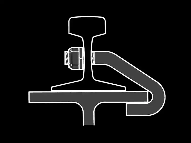
Hook bolts are typically installed in opposing pairs on both sides of the rail to provide balanced restraint.
One key advantage of this method is that it requires neither drilled holes in the beam flange nor welded rail clamp bases. However, holes must be pre-drilled in the rail web to accommodate the hook bolts.
Hook Bolt Installation Steps
Step 1: Measure the Beam Flange Dimensions
Measure the width, thickness, and edge profile of the beam flange to confirm that the hooks can engage the flange properly and provide sufficient contact.
The hook opening must match the beam flange thickness. An opening that is too large may result in insufficient engagement, while one that is too small may prevent proper installation.
Step 2: Drill the Rail Web Holes
Determine the hole positions, diameters, and spacing on the rail web according to the rail section and hook bolt dimensions.
The holes must be positioned to avoid interference with fishplate bolt holes and other features that could affect rail strength. Adequate edge distances and web cross-sectional strength must also be maintained.
Drilling should be completed during rail processing according to approved drawings. Do not use on-site flame cutting to make these holes.
Step 3: Install the Hook Bolts
Place the rail on the steel beam and align its centerline with the specified installation position.
Insert the hook bolts through the pre-drilled rail web holes, ensuring that each hook fully engages the edge and underside of the beam flange.
Install the hook bolts in opposing pairs as specified in the design to maintain balanced clamping.
Step 4: Tighten and Inspect
Install the washers, nuts, and locking components, then tighten the assembly according to the bolt specifications and approved installation requirements.
After tightening, check the following:
- Each hook fully engages the beam flange.
- The bolts are correctly positioned without misalignment.
- The rail foot maintains adequate contact with the supporting surface.
- The bolts on both sides are properly installed and tightened.
- The rail position and gauge meet the installation requirements.
Regular inspections are necessary during service to check for loose nuts, bolt elongation, and deformation around the rail web holes.
What Types of Cranes Are Suitable for Hook Bolts?
Hook bolts are not a universal replacement for rail clips on heavy-duty crane runways.
They are primarily used for light rail sections and light-duty crane applications. Their use should be carefully evaluated under the following conditions:
- High-frequency, heavy-duty cranes, such as CMAA Classes D, E, and F.
- Cranes with rated capacities exceeding 20 US tons (approximately 18.1 metric tonnes).
- Long runway systems exceeding 500 ft (approximately 152 m).
Repeated loading may cause hook bolts to loosen or the rail web holes to elongate over time. Their fixing arrangement also offers limited accommodation for longitudinal thermal movement of the rail.
Therefore, hook bolts are more suitable for light-duty, relatively short runway systems where regular inspection and maintenance can be provided.
For heavy-duty cranes or high-frequency operating conditions, hook bolts should not be selected based on dimensional compatibility alone, even when they can physically be installed.
4. How to Choose Crane Rail Fasteners for Different Beam Widths
| Beam Width and Installation Conditions | Recommended Option to Evaluate | Selection Criteria |
|---|---|---|
| The beam flange meets the minimum width requirement for standard WJK clamps | Standard WJK | Conventional welded installation |
| Standard WJK clamps cannot be installed, but the beam flange meets the minimum width requirement for SWJK | SWJK compact rail clamps | Reduced mounting width and installation height |
| SWJK clamps cannot be accommodated, but the beam flange edge can be engaged by hooks and the crane operates under light-duty conditions | Hook Bolts | No welded clamp bases or drilled holes in the beam flange are required |
| The beam flange is narrower than the rail foot | Evaluate the rail support structure first | Fastening components cannot compensate for insufficient rail support width |
| The beam is too narrow and the crane operates under heavy-duty, high-frequency conditions | Reassess the supporting structure and develop a dedicated fastening design | Do not force the use of hook bolts under unsuitable operating conditions |
The key difference between these two solutions is:
SWJK addresses limited mounting space for rail clamps, while Hook Bolts use a different connection method to secure the rail when the beam flange cannot accommodate conventional clamp bases.
Neither solution eliminates the need to verify the rail support conditions and the load-bearing capacity of the steel beam.
5. Glory Track’s Engineering Recommendations
When the beam flange is too narrow to accommodate standard rail clips, Glory Track recommends first checking the rail section and actual beam dimensions to determine the available mounting space. The fastening method should then be selected based on the crane’s operating conditions.
If neither of the two solutions discussed in this guide meets the project requirements, a structural engineer should reassess the steel beam and rail support structure. Reducing clip dimensions or changing fixing positions without proper verification is not a reliable solution.
Get Help Selecting the Right Crane Rail Fastening Solution
To evaluate whether SWJK rail clamps or Hook Bolts are suitable for your project, provide Glory Track with the following information:
- Rail Type: Rail section and foot width.
- Beam Flange: Top flange width, thickness, and beam cross-sectional drawing.
- Crane Duty: Rated lifting capacity, maximum wheel load, and lateral load.
- Installation Conditions: Whether welding is permitted, whether holes can be drilled in the rail web, and the available installation clearance.
Based on these details, Glory Track can help identify suitable rail fastening components and provide the corresponding installation dimensions and technical recommendations.
A narrow steel beam does not necessarily prevent secure crane rail installation. The key is to select a fastening method that matches the beam section, rail type, and crane operating conditions.